
Phase balancing and harmonic mitigation before, during and after augmentation
Summary
Low voltage augmentation adds capacity and lowers impedance. It does not redistribute load between phases, and it does not remove harmonic current from the network. Both problems are growing on distribution networks for the same reason augmentation is being triggered in the first place: single-phase rooftop PV, single-phase EV charging, and inverter-connected load.
An LV D-STATCOM should therefore be specified as a permanent network asset. It performs two functions, continuous phase balancing and active harmonic filtering. No passive augmentation performs this at any cost, and the drivers behind both intensify as a feeder’s load and inverter population grow. Deployed early, it releases capacity from conductors and transformers that are already in the ground. After augmentation eventually proceeds for thermal reasons, it continues to manage the conditions the augmentation was never able to address.
This release sets out the engineering behind that position.
1. Augmentation changes impedance, not composition
Conventional LV remediation works through impedance. Reconductoring increases conductor cross-section. A larger distribution transformer presents a lower source impedance. Splitting a feeder or adding a substation shortens the electrical distance to the worst-served customer. In each case the voltage consequence of a given current is reduced.
Phase imbalance is not a function of impedance. It is a function of how load and generation are distributed across the three phases, and of how that distribution varies through the day. Connection schedules are balanced at design. Real-time loading is not. Diversity between customers, uneven single-phase PV, and the arrival of 7 kW single-phase EV chargers all produce unequal phase currents on a nominally balanced feeder.
Augmentation attenuates the symptom. The neutral current that flows because of unequal phase loading is unchanged by a larger conductor; the voltage difference it produces between phases is reduced, in proportion to the impedance reduction achieved. Where the imbalance is severe, that reduction may not be sufficient. Where load subsequently grows — and augmentation is generally triggered by load growth — the voltage consequence returns.
An LV D-STATCOM addresses the current, not the voltage drop it produces. The EcoVAR transfers real power between phases through its DC link, drawing from the lightly loaded phases and supplying the heavily loaded one. The phase currents seen upstream of the point of connection are equalised. This is a continuous, closed-loop function that follows the load pattern through the day. No passive asset can do this.
2. Hosting capacity is set by the worst phase, not the average
Where single-phase PV is unevenly distributed, the normal case, since installation follows customer decisions rather than network planning, the constraining phase reaches the upper statutory voltage limit while the other two retain headroom. Under AS 4777.2, inverters on the constrained phase respond with volt-watt curtailment. Export is lost on one phase while capacity sits unused on the others.
Augmentation raises hosting capacity uniformly across all three phases. It does not correct the asymmetry, so the worst phase remains the binding constraint. The headroom already present on the other phases stays inaccessible.
Phase balancing recovers that headroom. By equalising the phase currents, the voltage rise is shared rather than concentrated, and the curtailment threshold on the worst phase is pushed back. The gain is available from the existing conductor, at the existing rating, without an outage.
This is the more significant point for a network with a mature rooftop PV population: the constraint is frequently distributional rather than absolute. Solving it distributionally releases capacity the utility has already paid for, and returns the benefit to every customer on the feeder rather than to those who happen to sit on the favourable phase.
3. Harmonic current is not removed by a larger conductor
Harmonic current injection on LV feeders is increasing from PV inverters, EV chargers, variable speed drives, switched-mode power supplies and LED lighting. The resulting voltage distortion is the product of the injected harmonic current and the network’s harmonic impedance at each order.
Lowering the source impedance through augmentation does reduce harmonic voltage distortion at the point of measurement, for a given injected current. That is a real benefit and worth stating plainly. It does not resolve the problem, for three reasons.
The current still flows. A lower impedance path means harmonic current propagates further upstream, through the distribution transformer and toward the MV network, rather than being attenuated locally. The distortion is relocated rather than removed.
Transformers still carry it. A replacement transformer carries the same harmonic load current and is subject to the same additional eddy current and stray losses. Thermal derating for harmonic content applies to the new asset as it did to the old one.
An active harmonic filter operates on the current directly. The EcoVAR measures the harmonic content at the point of connection and injects compensating current in counter-phase, so the distorted current is cancelled locally and does not propagate upstream. This function is independent of network impedance, and therefore unaffected by whether augmentation has been carried out. Its 864 V DC link provides the voltage headroom needed to slew injection current fast enough to track higher-order components, and to retain full capability at the top of the statutory voltage range.
4. Deployment: same day, no outage, utility-controlled
The operational profile is as important to the case as the electrical performance, because it is where the contrast with augmentation is widest.
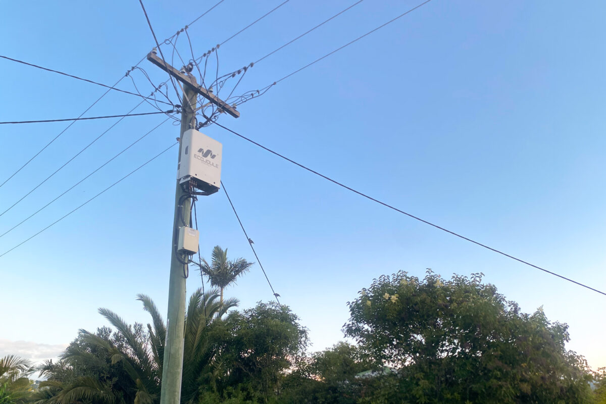
The EcoVAR is pole-mounted and connects in parallel through a set of LV fuses. Installation is carried out live. No customer outage is required, no switching programme, no civil work, no customer notification cycle. A crew installs and commissions in a single visit, on the same day the unit arrives on site.
Once energised, the unit is the utility’s asset in every operational sense. It logs phase voltages, currents, neutral current and harmonic content continuously. Settings are adjusted and firmware updated remotely, by the utility, without a site visit. There is no dependency on the manufacturer for routine operation, and no scheduled maintenance to programme.
Set against an augmentation that requires design, approval, procurement, outage planning and construction — and a capital cost one to two orders of magnitude higher — the D-STATCOM is a decision that can be made and executed inside the time it takes to scope the alternative.
5. Sequencing across the feeder’s life
The functions above suggest an order of works rather than a choice between alternatives.
Deploy on the existing network. Where a feeder shows voltage excursions with a significant imbalance component, an EcoVAR increases the usable capacity of the conductors and transformer already installed. Endeavour Energy and Ausgrid crews are completing installations in under two hours. Voltage complaints and PV curtailment are addressed on a timescale of weeks.
Augment when the constraint is genuinely thermal. Load growth eventually consumes the headroom that balancing releases. When the limit is the current-carrying capacity of the conductor or the rating of the transformer, augmentation is the correct answer and a D-STATCOM is not a substitute for it.
The D-STATCOM continues. At this point the feeder carries more load, more PV and more inverter-connected equipment than when the unit was installed. The imbalance and harmonic drivers are stronger, not weaker. The EcoVAR continues to perform phase balancing and active harmonic filtering — the two functions the augmentation did not deliver — on a network that now needs them more. It also continues to log at that point, which for most utilities represents a rare permanent measurement location in the LV network.
The unit’s role broadens over the life of the feeder: constraint relief first, then power quality management and network visibility. It is specified once and it stays.
6. Understanding Siting of the EcoVAR
Siting is not among the constraints, and a few spans either side of the worst-served customer makes little practical difference. The unit does not warrant a detailed siting study. Given the STATCOM exploits upstream impedance, most installations range between halfway and ¾ of the way down an LV feeder. On a cost effective asset such as the EcoVAR, displacing works that cost orders of magnitude more, engineering effort spent optimising position is effort spent for no return. More detail on site selection is covered here: Site Selection for the EcoVAR D-STATCOM: Optimising Placement
7. Identifying a candidate feeder
The indicators are measurable and most utilities already hold the data. This is a screening exercise of minutes, not a study:
- Voltage excursions on the feeder. If it’s 3 phase excursions, the STATCOMs reactive compensation manages it. Imbalance is managed by the combination of Reactive and Active Power Transfer
- Uneven single-phase PV and EV Charger distribution across phases
- Rising voltage total harmonic distortion, or customer equipment complaints without a corresponding thermal constraint
Where any of these indicators are present, a single unit on a live feeder produces measured before-and-after evidence from the utility’s own network within weeks — at a fraction of the augmentation cost, and with no outage required to obtain it.
EcoJoule Energy designs and manufactures the EcoVAR LV D-STATCOM in Brisbane, Australia.