
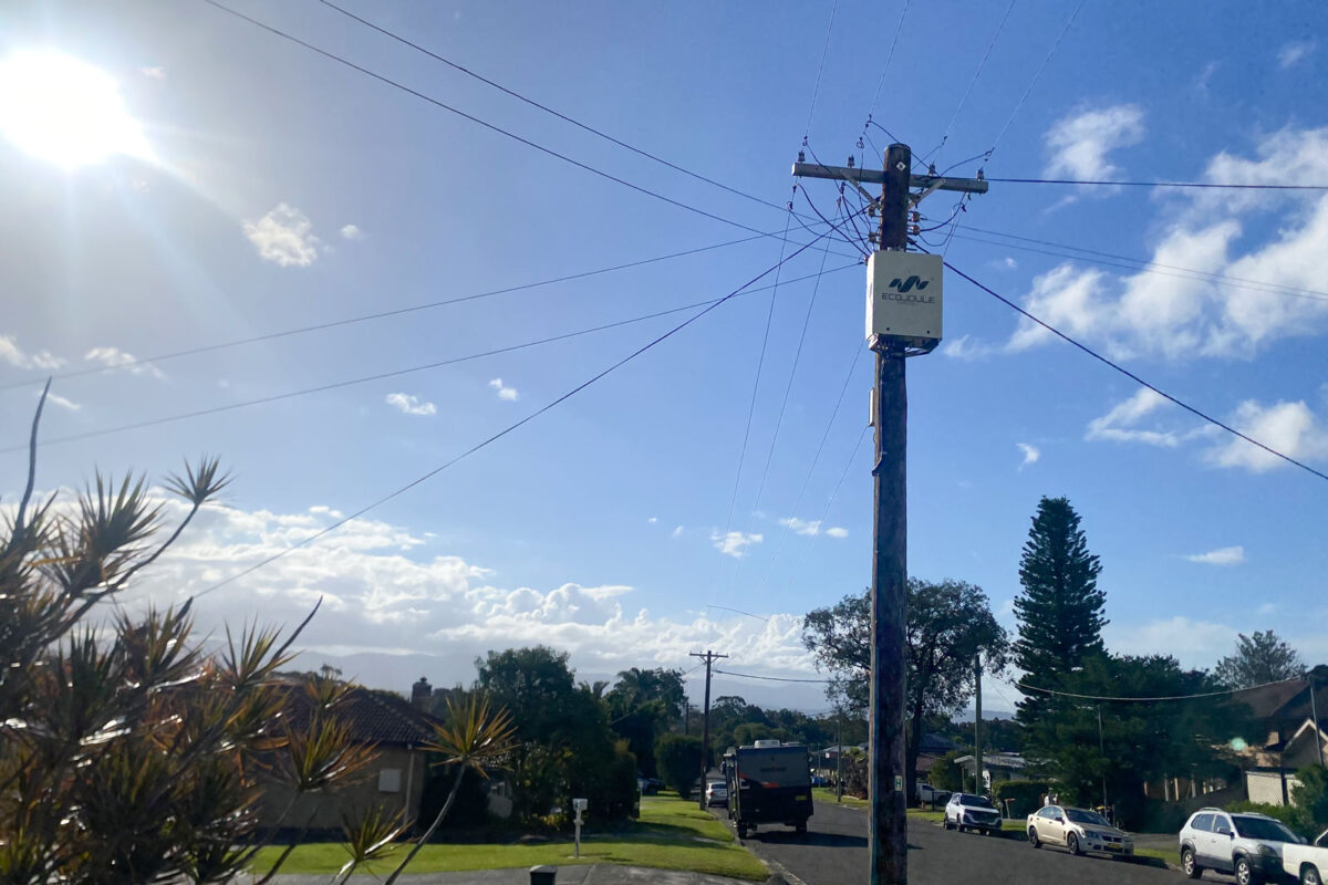
How the two simultaneous control loops in a three-phase LV STATCOM work, and what each one can and cannot correct.
1. Summary
- The EcoVAR uses three independently controlled single-phase inverter stages connected to one shared DC bus.
- A Volt-VAR droop curve sets reactive power as a function of measured voltage. The EcoVAR evaluates that curve against each phase voltage separately, so one phase can absorb VArs while another injects them.
- A second loop, Active Power Balancing, runs at the same time. It moves real power from lightly loaded phases to heavily loaded phases through the shared DC bus.
- The two loops correct different things. Reactive power shifts each voltage as well as the average voltage; active power transfer corrects the difference between phases and reduces neutral current. Neither substitutes for the other.
- Both loops operate from voltage measurement only. No series current transformers are required, so installation does not depend on breaking the conductor.
2. What a Volt-VAR droop curve does
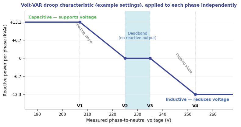
A Volt-VAR droop curve is a piecewise-linear rule that converts a measured voltage into a reactive power command. It is defined by four voltage set points and applied continuously, without operator intervention or a network communications link.
Below the lower set point the STATCOM sources reactive power (capacitive operation), which raises voltage at the point of connection. Above the upper set point it sinks reactive power (inductive operation), which lowers voltage. Between the two inner set points the output is zero. That deadband stops the unit from responding to normal small voltage variations.
The EcoVAR follows the generator sign convention: a positive reactive power reference is capacitive (sourcing VArs), a negative reference is inductive (sinking VArs). The characteristic is as described in AS/NZS 4777.2:2020 and similar international standards like EN50549, with leading and lagging slopes that can be set symmetrically or asymmetrically.
3. Configurable set points
All four set points are user-configurable from the EcoVIEW engineering tool or by uploading a settings file through EcoFLEET Manager. A limited set is also available over DNP3 and Modbus.
| Set point | Range | Function |
| V1 | 180 – 225 V | At and below V1 the phase holds maximum capacitive output. |
| V2 | 185 – 250 V | Lower edge of the deadband. Capacitive output falls linearly from V1 to zero at V2. |
| V3 | 185 – 260 V | Upper edge of the deadband. Inductive output starts here. |
| V4 | 190 – 277 V | At and above V4 the phase holds maximum inductive output. |
Rated output is 40 kVAr total, 13.33 kVAr per phase, available in both directions across 210 V to 277 V. The unit continues to operate down to 180 V at a maximum continuous 63.5 A per phase, and tolerates connection to any voltage from 0 V to 280 V without damage.
4. Three inverter stages, one DC bus
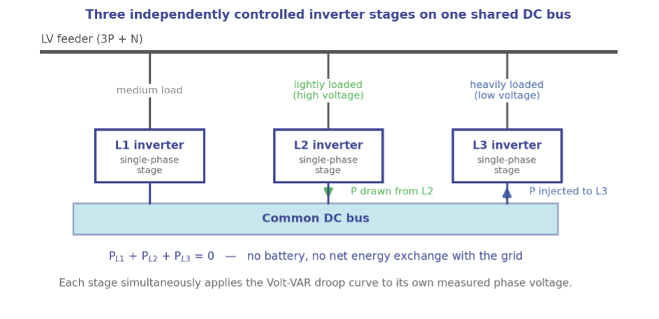
The EcoVAR is not a single three-phase bridge producing a balanced output. Each phase is served by an inverter stage with its own current control loop, and all three stages are connected to a common DC bus. Two consequences follow directly from that architecture.
First, each stage can be commanded independently. The droop curve is evaluated three times each control cycle, once per phase, against that phase’s own measured phase-to-neutral voltage. One phase reaching its current limit does not constrain the other two.
Second, active (real) power can be moved between phases. Because the three stages share a DC bus, power drawn from one phase can be injected into another without a battery and without any net exchange of energy with the network.
5. A single characteristic, three independent evaluations
The three phases share one droop characteristic — the same four set points and the same slopes apply to all of them. What is independent is the input and the output, not the configuration. Each stage measures its own phase voltage and produces its own reactive power command from the shared curve.
This is what allows the EcoVAR to reduce voltage unbalance rather than simply shift the whole voltage profile. On a feeder where L1 sits at 252 V under high PV export and L3 sits at 228 V under load, the same curve puts L1 into full inductive operation and L3 into capacitive operation at the same instant.
The unit can alternatively be configured to act on the average of the three phase voltages. That mode is available for networks whose standards require it, but it gives a poorer voltage outcome for customers and is not the recommended setting.
6. The second loop: Active Power Balancing
Reactive power alone corrects voltage well on reactive networks. On resistive LV networks — underground cable, long aluminium mains, heavily loaded urban feeders — voltage responds more strongly to real power than to reactive power, and reactive injection alone cannot bring the phases together.
Active Power Balancing addresses this. The EcoVAR takes the three phase voltages as a proxy for phase loading: a higher voltage implies a lighter load, a lower voltage implies a heavier one. It then transfers real power from the lighter phases to the heavier ones in proportion to the voltage differences, subject to the constraint that the three phase powers must sum to zero. This reduces current unbalance on the feeder and neutral current at the transformer.
Using voltage as the proxy avoids series current transformers. That removes both the cost and the outage that a CT installation would otherwise require.
Two modes are provided. Gain-based transfer injects real power per phase in proportion to the deviation from the average voltage, with a user-selected P or Q priority that determines which is curtailed first if a phase reaches its apparent power limit. Optimal X/R computes a reference apparent power per phase from a voltage droop and then splits it into active and reactive components according to the source impedance X/R ratio, which is taken from the network model or estimated at commissioning. Active Power Balancing is disabled by default and is enabled per site.
7. Why both loops are needed
The two loops are subject to different constraints, and that is the whole reason for running them together.
| Volt-VAR droop (Q) | Active power balancing (P) | |
| Quantity controlled | Reactive power per phase | Active power transfer between phases |
| Network constraint | Limited only by the per phase apparent power rating of the unit | Sum of the three phase powers must be zero |
| Effect on average voltage | Can raise or lower all three phases together | None — the three voltage changes sum to zero |
| Effect on unbalance | Reduces it, most effectively on reactive networks | Reduces it, most effectively on resistive networks |
| Effect on neutral current | Indirect | Direct reduction at the transformer |
| Default state | Enabled | Disabled — enabled per site |
If all three phase voltages are high, transferring real power between them cannot bring any of them down, because whatever one phase gains another must lose. Only reactive power can move the average. Conversely, on a resistive feeder with one badly loaded phase, reactive power struggles to close the gap and real power transfer does it efficiently. Running both loops covers both cases across the full range of LV network impedances.
8. Control loop timing
| Function | Response |
| Internal current control loop | 10 – 90% rise and fall in 2 ms or less |
| Volt-VAR droop response (ramp-rate limited) | Default 5 s, to keep the steady-state response smooth. However, can be set sub-cycle for fast response, typically when Active Power Balancing is disabled. |
| Voltage sag and swell limiting | 10 ms time constant; overrides the droop response |
| Reactive current overshoot | No more than 5% of steady-state output |
The current loop is fast enough to respond within a tenth of a cycle. The droop response is deliberately slowed to five seconds so that the unit regulates steady-state voltage rather than chasing transients. Fast events are handled separately: if a phase reaches 180 V or 277 V, the sag and swell function commands maximum reactive power with a 10 ms time constant and overrides the droop.
9. What to specify at commissioning
- Four droop set points, plus symmetrical or asymmetrical slopes.
- Per-phase control enabled, or average-voltage mode if a network standard requires it.
- Active Power Balancing: disabled, gain-based, or optimal X/R.
- For gain-based operation: P priority or Q priority, chosen from the local X/R ratio — Q priority for overhead and other reactive feeders, P priority for cable and other resistive feeders.
- For optimal X/R operation: the X/R ratio, from the network model or estimated during commissioning.
For settings files, network studies or a copy of the EcoVAR ALTO user manual, contact EcoJoule Energy at sales@ecojoule.com or your regional distributor.