
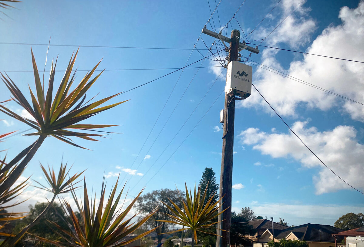
Why service reallocation and augmentation no longer hold balance on feeders with single-phase EV charging, heat pumps and rooftop PV — and what a three-converter D-STATCOM does differently.
Phase imbalance on low voltage networks is not new. What has changed is the size and behaviour of the loads creating it, and the rate at which a balanced feeder becomes an unbalanced one.
Imbalance is now a load-growth problem
Australian LV distribution is a four-wire multiple earthed neutral system, and almost every domestic connection is single phase. Historically that was manageable: individual loads were small, diversity across dozens of customers smoothed the per-phase totals, and a planner could allocate services across phases at connection and expect that allocation to hold for a decade.
Single-phase 7.2 kW EV chargers, heat pumps, electric hot water, reverse-cycle air conditioning and residential batteries break that assumption. One EV charger can represent more after-diversity demand than the five houses around it. Loads arrive where customers buy them, not where the network has headroom, and they cluster. One street adopts, the next does not. A feeder that measured within a few percent of balance at commissioning can sit 30 to 40 percent out on a winter evening, where the cold climate means that load diversity is simply all feeder heat pumps operating. Conversely, the imbalance moves during the day, as charging, hot water and cooling cycles overlap.
Why imbalance presents as a voltage problem
Unbalanced phase currents return through the neutral. In an MEN system the neutral is not a zero-volt reference; it carries current and develops a voltage along its length. That neutral shift moves the star point relative to the customer connections, so the heavily loaded phase drops further than its own load would explain, and the lightly loaded phases rise. The customer on phase C experiences a voltage complaint caused by loads on phase A.
The loss penalty follows the same currents.
| Condition | Phase currents | Neutral current | Conductor loss term |
| Unbalanced | 100 A / 60 A / 40 A | 53 A | 18,000 A² |
| Balanced | 66.7 A each | 0 A | 13,333 A² |
Same total current delivered, unity power factor, equal phase and neutral conductor resistance. Balancing removes the neutral current and reduces conductor loss by approximately 26 percent.
WORKED EXAMPLE
1. Neutral current is the phasor sum, not the arithmetic sum
Ia = 100 A at 0°    Ib = 60 A at −120°    Ic = 40 A at +120°

Real      = 100 − 30 − 20 = 50.0 A

Imaginary = −51.96 + 34.64 = −17.32 A

|In| = √(50.0² + 17.32²) = 52.9 A
2. Loss term is ΣI² across all four conductors
Unbalanced: 100² + 60² + 40² + 52.9² = 18,000 A²

Balanced:   3 × 66.7² + 0²            = 13,333 A²

Reduction:  1 − 13,333 / 18,000 = 25.9%
3. Symmetrical component view
Positive sequence         66.7 A  →  13,333 A²

Negative sequence         17.6 A  →     933 A²

Zero sequence (phases)    17.6 A  →     933 A²

Zero sequence (neutral)   52.9 A  →   2,800 A²
Positive sequence is the component doing useful work. The remaining 4,667 A² is the imbalance penalty, and the EcoVAR removes it by cancelling the negative- and zero-sequence components. Figures are conductor loss in the LV section only, at unity power factor with equal phase and neutral conductor resistance; they exclude converter losses. Where the neutral is of reduced cross-section relative to the phases, the penalty is larger than shown.
The distribution transformer is derated by the same mechanism: it reaches its thermal limit on the worst phase, not on its nameplate kVA. Imbalance therefore consumes three things a planner needs — voltage headroom, thermal capacity and network losses. It also consumes hosting capacity, because the same neutral shift that pulls one phase low pushes another high, and rooftop PV on that phase curtails first.
What traditional balancing achieves, and where it stops
Service reallocation. A crew measures the pillar or the transformer over a week, identifies the loaded phase, and moves services across. It works, and it is inexpensive. It also requires a truck, a customer outage and a decision based on a snapshot. The measurement describes last month’s load pattern. The next EV connection, the next hot-water changeover or a shift in occupancy reverses it. Networks that rebalance on complaint are rebalancing the same feeders repeatedly.
Augmentation. A second transformer, reconductoring, or splitting the LV area fixes the peak with certainty. It also costs capital, takes months of design, easement and outage planning, and is sized for a load forecast that single-phase electrification keeps revising upward.
Conventional three-phase STATCOMs. A standard three-leg converter injects a balanced positive-sequence current. It can raise or lower all three phase voltages together, and it can correct power factor, but it cannot differentiate between phases. Applied to an unbalanced feeder it lifts the low phase and the already-high phases with it.
Three converters, one DC bus
The EcoVAR is built as three independent single-phase STATCOM systems sharing a common DC bus. That architecture is the reason it can do something a conventional STATCOM cannot.
Because each phase has its own converter, the units can operate in opposite directions at the same instant. The converter on the heavily loaded phase supplies active power to the network; the converters on the lightly loaded phases absorb it. The shared DC bus is the transfer path. Net real power exchange with the network is close to zero, but the currents drawn from the transformer and the upstream conductor are balanced.
Active power balancing control manages this continuously. There are no discrete steps to select and no transformer taps to move. The device sets per-phase active and reactive current targets from the instantaneous measured condition and holds balance as the load profile changes through the day.
Sub-cycle response and motor starts
The control operates on instantaneous per-phase quantities rather than RMS values averaged over seconds, so correction occurs within a cycle.
This matters most for motor starting. A heat pump or air conditioning compressor draws several times its running current for a few cycles at start. On a weak single-phase connection that inrush produces a visible voltage dip, and through the neutral shift it disturbs the other two phases as well — the sag propagates to customers who did not cause it. A balancer that responds over seconds sees the event only after it has finished.
The EcoVAR supports the starting phase from the DC bus as the current rises, so the dip is contained at its source and does not couple across. The same mechanism handles PV inverter ramps, battery mode changes and EV charger step loads.
What the planner gets
- Balanced phase currents at the distribution transformer, held continuously rather than set once.
- Neutral current and neutral voltage rise reduced, with the associated loss reduction.
- Voltage spread between phases narrowed, recovering headroom for both load and PV export.
- Sub-cycle containment of motor starts and step loads.
- Installation on an energised network with no customer outage.
- Per-phase measurement of the LV condition, available remotely, including after the correction is in service.
Phase imbalance created by single-phase electrification is dynamic. It changes hour to hour and grows year on year. Correction that is set manually, or that responds in seconds, is answering a question the network stopped asking. Dynamic balancing addresses it at the timescale it occurs, on the existing poles and wires.
ABOUT ECOJOULE ENERGY
EcoJoule Energy designs and manufactures low-voltage grid-edge power electronics in Brisbane, Australia. Its EcoVAR LV D-STATCOM is in field service with distribution utilities in Australia and internationally, and is available in pole-mount (EcoVAR Alto) and ground-mount (EcoVAR Terra) variants. EcoJoule’s technology relieves grid congestion and increases network hosting capacity, allowing the benefits of the energy transition to reach more users of the existing distribution network.