The EcoVAR runs Volt-VAR droop and active power phase balancing at the same time. A priority setting decides which control gives way when a phase reaches its rating. Matching that setting to the X/R ratio of the network gets more correction from the same unit.
Two controls, one rating
Volt-VAR droop. Each phase injects capacitive VARs when its voltage is low and absorbs inductive VARs when it is high, with a configurable dead band around nominal. All three phases share one droop curve but respond to their own measured voltage, so one phase can inject while another absorbs.
Active power phase balancing. The EcoVAR draws active power from the high-voltage (lightly loaded) phase and returns it to the low-voltage (heavily loaded) phases. It has no energy store, so the three phase active powers always sum to zero. Phase voltage is the proxy for phase loading, so no series CTs are needed. Balancing also reduces neutral current back to the transformer.
Control
Corrects voltage unbalance
Corrects average voltage
Volt-VAR droop (Q)
Yes, per phase
Yes
Active power balancing (P)
Yes
No: P₁ + P₂ + P₃ = 0
If all three phases are high, for example during midday solar export, active power balancing cannot lower them. Only reactive power absorption can.
Priority modes and when to use them
Both controls run continuously. The priority setting acts only when a phase reaches its apparent power limit, and decides which control is curtailed.
Setting
Capacity first to
Remaining capacity to
Suited to
Q-Priority
Volt-VAR droop
Phase balancing
Reactive networks (higher X/R): overhead feeders with a significant reactive component; sites close to the transformer
Where X dominates, a VAR moves voltage further than a watt. Where R dominates, a watt moves voltage further than a VAR. P-Priority is most effective where low X/R coincides with significant phase imbalance, such as single-phase rooftop solar or EV charging concentrated on one phase.
The priority can be changed remotely through the EcoFLEET™ Fleet Manager after commissioning. Parameter details are in section 5.4 of the EcoVAR User Manual.
EcoJoule Energy’s Network Planners’ Guide explains how D-STATCOM technology provides network planners and engineers with a faster, more flexible and lower-cost alternative to conventional network augmentation, while improving voltage regulation, phase balance and power quality across increasingly complex distribution networks.Download the full guide here.
Executive Summary
Low-voltage electricity networks are under growing pressure from rooftop solar, electric vehicles, electrification and other distributed energy resources (DER), while much of the infrastructure supporting them was designed for a very different energy system.
The resulting overvoltage, undervoltage, phase imbalance, and power quality issues do not always indicate that a network has run out of capacity. Where the constraint is voltage or imbalance rather than thermal capacity, LV D-STATCOM technology such as EcoJoule Energy’s EcoVAR™ can provide a faster, more flexible alternative to traditional augmentation.
EcoVAR can be installed in approximately two hours with no customer outage, avoiding much of the engineering, construction and disruption associated with traditional network upgrades. In the illustrative example examined in this paper, the D-STATCOM solution delivers an annualised cost that is approximately 2.98 times lower than that of traditional augmentation. It can also defer major capital works and be redeployed as network requirements change.
The opportunity is not to replace augmentation where additional thermal capacity is genuinely required. It helps match investment to actual constraints, solve problems sooner, deploy capital more efficiently, and get more from existing network infrastructure.
D-STATCOM or Traditional Augmentation?
Traditional augmentation means reconducting LV lines, installing new transformers, or extending the medium-voltage supply to split feeders and shorten LV runs. Manual phase balancing, moving single-phase customer connections between phases, is also a form of augmentation.
A D-STATCOM is a form of augmentation. It requires no new HV line, no outage, and installation is under two hours. The engineering design is standard for all installations on a given network.
The limitation is explicit: a D-STATCOM does not add thermal capacity. Only augmentation does that.
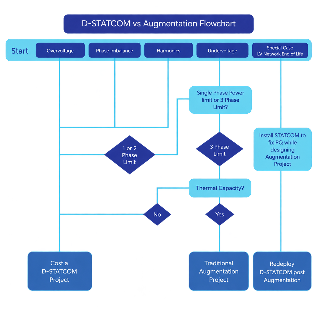
Most voltage, imbalance and harmonic problems can be resolved without adding capacity. That is the selection test.
Three differences matter to a planner.
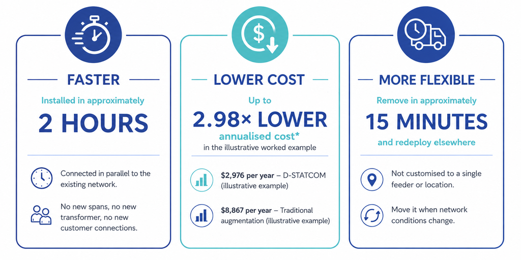
1. Speed – Connected in parallel to the existing network. No new spans, no new transformer, no new customer connections. Installed and commissioned in two hours. Augmentation projects run in days or weeks and include a customer outage.
2. Project Cost – The unit cost is comparable to that of a single transformer. The difference is the project around it: engineering design, outage management, traffic management, and construction lead time.
3. Redeployment – When capacity becomes the binding limit, an installed D-STATCOM can be moved. It is not customised to a site. Removal takes 15 minutes, and reinstallation takes two hours. Augmentation is fixed to the site where it is built.
Where a D-STATCOM Applies
A D-STATCOM, such as EcoJoule Energy’s EcoVAR, connects in parallel with the existing LV network and directly addresses voltage imbalance and harmonic problems. The technology is particularly applicable where the network is experiencing:
Overvoltage – Often associated with high levels of rooftop PV exporting onto an LV feeder.
Phase imbalance – Created when load and generation are unevenly distributed across the three phases.
Harmonics – Increasingly relevant as inverter-based and power-electronic devices proliferate.
Undervoltage on one or two phases – Where available capacity exists elsewhere across the three-phase network.
Voltage sags, swells and flicker – Where dynamic voltage support can improve local power quality.
Selection Guide
Observed problem
Outcome
Reason
Overvoltage
Cost a D-STATCOM project
Active power is not the limit, so the device always has authority.
Phase imbalance
Cost a D-STATCOM project
At least one phase carries excess active power. Active phase transfer corrects it.
Harmonics
Cost a D-STATCOM project
Harmonic correction is not limited by active power.
Undervoltage on one or two phases
Cost a D-STATCOM project
A single-phase power limit. Correctable by transfer between phases.
Undervoltage on all three phases
Traditional augmentation project
A thermal capacity limit. A D-STATCOM does not add capacity.
LV network at end of life
Both, in sequence
Install the D-STATCOM to hold power quality while the augmentation is designed, then redeploy it.
Calculating the Benefits
The real cost of solving an LV network constraint extends well beyond the upfront price of the equipment.
Traditional augmentation may deliver infrastructure with an asset life measured in decades, while a D-STATCOM has a shorter life but offers something conventional infrastructure cannot: the flexibility to be removed and redeployed as network needs change.
A simple capital-cost comparison therefore does not compare like with like. A more meaningful approach is to compare the cost of delivering the required network outcome over time.
Equivalent Annual Cost (EAC) provides that comparison by annualising each component according to its cost, expected asset life and discount rate:
EAC = C ÷ [(1 − (1 + r)^-n) ÷ r]
Each project component retains its own asset life, allowing long-life infrastructure, engineering, installation and equipment costs to be assessed consistently. This provides planners with a clearer picture of the long-term economics of each approach rather than focusing solely on initial capital expenditure.
The Value of Deferring Augmentation
The decision is not always D-STATCOM or traditional augmentation. Where additional thermal capacity will eventually be required, a D-STATCOM can address the immediate voltage or phase constraint while allowing major augmentation to occur when that additional capacity is actually needed.
Deferral can postpone significant capital expenditure, potentially move investment into a future regulatory period and provide more time to understand how DER penetration and demand will develop.
Importantly, the investment does not have to become stranded when augmentation eventually occurs. If the D-STATCOM still has useful service life, it can be redeployed to another constrained feeder, extending the value of the original investment.
The objective is not to avoid necessary augmentation. It is to solve today’s constraint efficiently, preserve future options and invest in permanent network capacity when the network actually needs it.
How a D-STATCOM Works
The D-STATCOM is a three-phase power electronic device connected to the LV network in parallel. It is three independently controlled inverter-STATCOMs, one per phase, with a common shared 864V nominal DC bus.
Two control actions run at the same time.
Reactive Injection – The unit exchanges reactive current with the network at the point of connection. The voltage change is approximately: ΔV ≈ Q·X / V, where Q is the injected reactive power, X is the upstream reactance and V is the nominal voltage. The unit works against upstream impedance. More upstream reactance gives more voltage authority.
Active Phase Transfer – The unit moves real power between phases through a shared DC bus. This corrects imbalance directly rather than compensating negative sequence current alone. Active harmonic filtering runs on the same hardware, injecting harmonic current in antiphase.
Expected Voltage Correction
Worked case: 95 mm² aluminium overhead conductor, R ≈ 0.32 Ω/km, X ≈ 0.29 Ω/km, X/R ≈ 1, 1 MVA distribution transformer, 40 kVAr device.
Distance from transformer
Voltage correction
As percentage
500 m
≈ 16 V
4.00%
750 m
≈ 22.5 V
5.60%
Transformer rating has little effect at the feeder end. At 750 m, line reactance is about 95% of total upstream reactance, so a 500 kVA and a 1 MVA transformer give nearly the same result.
Two limits apply. Reactive injection does not correct voltage drop caused by real load current through line resistance. On an underground cable, X/R is lower and correction per kVAr is lower than the figures above.
D-STATCOMs still work in both cases, but the total voltage change per unit may be lower. Multiple STATCOMs can be connected to the same LV network to increase power if necessary. It is rare, even on aerial bundled conductor (ABC) networks, to need more than one 40 kVAr unit per LV feeder.
Site Selection
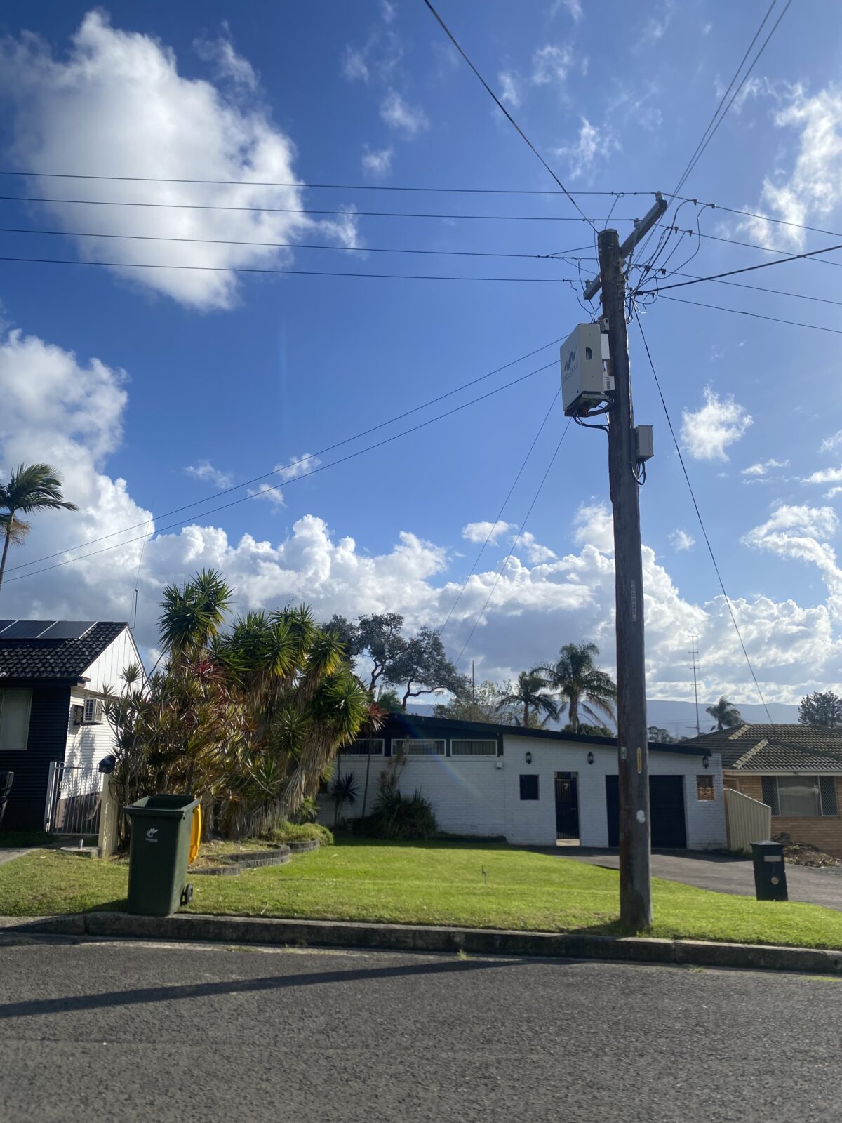
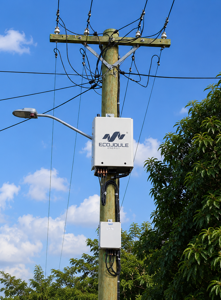
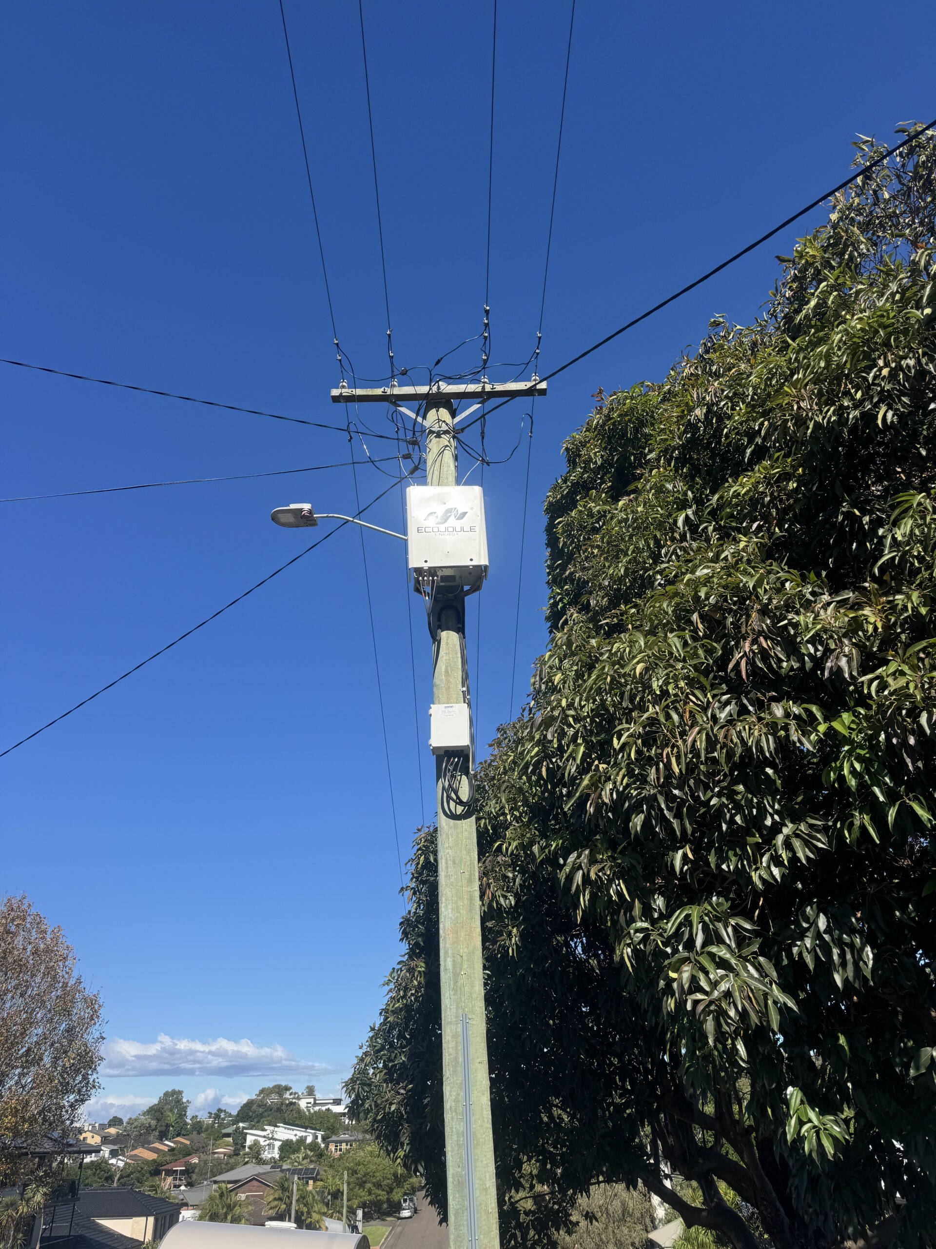
Place the unit near the voltage or imbalance problem. Most installations fall between 50% and 80% of the way along the LV feeder, but that range is a guide rather than a rule. Position follows the problem.
Move toward 50% where PV generation is concentrated in the middle of the feeder, or where the LV line can be backfed. Move toward the far end where the deviation is worst at the end. A shift of a few spans either direction makes no material difference to the result.
Within that zone, select the cheapest site to build. Where the electrically preferred pole carries streetlighting, fuses or telecommunications equipment, or where vegetation restricts access, move to the next clean pole. Installation cost dominates the difference; electrical position does not.
Where smart meter data is available, use it to identify the spans and phases with the most frequent and most severe deviations. This reduces selection to a short list of candidate poles.
Voltage is held closest to setpoint at the point of connection, but the effect is seen along the whole feeder.
A head-end tap changer translates the entire profile: it can be set for midday or for evening, not both. A D-STATCOM at the constrained node holds that node at setpoint and reverses between absorbing and injecting as conditions change.
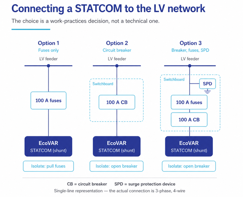
Connecting a D-STATCOM to the Network
The unit connects in shunt. The feeder continues to carry its load and does not need to be de-energised to connect or remove the unit. There is no customer outage.
Every shunt connection needs overcurrent protection and a means of isolation. Three arrangements are used. All three perform identically. The choice is a work practices decision, not a technical one.
Arrangement
Isolation method
When it is used
Outdoor fuses
Pull the fuses
Lowest cost, fewest components. Not available where technicians may not pull live LV fuses.
Switchboard with circuit breaker
Open the breaker
Where live fuse pulling is prohibited by work practices.
Switchboard with breaker, backup fuses and SPD
Open the breaker
Where surge protection is required by network standard.
Rating is 100 A, whether fuse or breaker. Rated current is 63.5 A continuous, with short-time capability of 1.5 × rated, approximately 95 A. Most off-the-shelf MCBs derate at elevated ambient temperature. At the unit’s 50°C maximum, a marginally sized breaker can trip at full output. A 100 A device holds margin above the derated threshold while remaining low enough to protect the connection. Confirm that the shunt connection conductors are rated to carry 100 A.
Notes for Protection Engineers
The D-STATCOM is not an energy storage device. It sources power from the line side. Loss of phase or loss of supply removes it from the circuit.
Onboard capacitors discharge over approximately one minute on loss of mains.
The protective device on the overhead connection is 100 A, fuse or MCB, subject to work practices.
Anti-islanding is handled by internal relays. Undervoltage and underfrequency disconnect settings are configurable and are shipped to IEC 62477 inverter settings.
As a utility-grade device, the disconnect range is often widened on commissioning. This allows the unit to correct voltage during a sag rather than disconnecting, and to connect to a non-compliant voltage and then bring it into compliance.
The tests highlighted in this white paper are intended to be run by the planner on network data and cost data that the planner controls.
A D-STATCOM will not suit every site. Where the constraint is thermal, it does not apply. Where it does apply, the annualised cost comparison should be run and recorded either way.
For More Information
Martin van der Linde Chief Commercial Officer EcoJoule Energy Pty Ltd sales@ecojoule.com
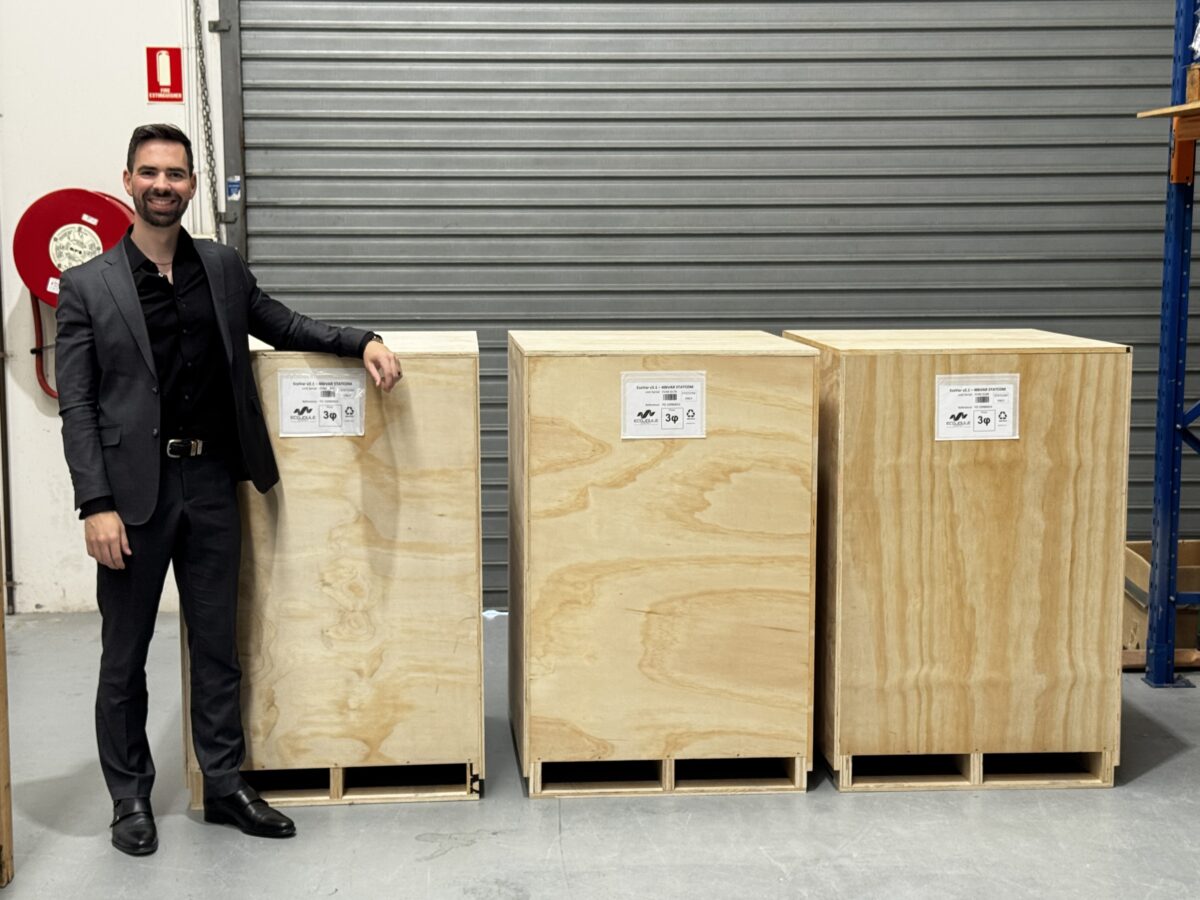
Australian energy grid technology company EcoJoule Energy has secured its first sale into Malaysia, marking another significant milestone in the company’s international expansion and adding one of Southeast Asia’s most important electricity markets to its growing global footprint.
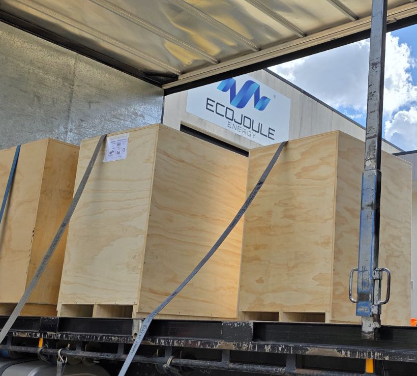
The sale to Tenaga Nasional Berhad (TNB), Malaysia’s national electricity company and operator of the electricity grid throughout Peninsular Malaysia and Kuala Lumpur, includes multiple EcoVAR™ ALTO pole-mounted STATCOMs and EcoSTORE™ pole-mounted Battery Energy Storage System (BESS) units.
The first shipment of EcoVAR units left Australia this week, with the EcoSTORE units to leave in approximately eight weeks.
The agreement further expands EcoJoule Energy’s international presence, which now spans almost ten countries, including Australia, New Zealand, Hong Kong, Belgium, Spain, the United Kingdom, Lithuania, Israel and now Malaysia.
EcoJoule Energy Founder and CEO Dr Mike Wishart said the new sale reflected growing global demand for technologies that help electricity networks manage the growth of renewable energy and the impact on the energy grid.
“Malaysia represents an important new market for EcoJoule and demonstrates the increasing international recognition of Australian innovation in electricity network management,” Dr Wishart said.
“Across the world, network operators are facing many of the same challenges. As solar penetration continues to increase, particularly on distribution networks, utilities need smarter and more flexible ways to manage voltage stability and power quality.”
“We are seeing strong demand for STATCOM technologies because they provide a highly effective solution for maintaining grid stability, while enabling greater levels of renewable energy integration.
“Utilities are looking for practical, cost-effective tools that help them manage the energy transition without relying solely on traditional network augmentation that can cost tens of millions of dollars.”
“The challenges facing electricity networks in Asia, Europe and Australia share a common theme – the transition to cleaner energy is creating increasingly dynamic and complex power flows. EcoJoule’s technologies are designed specifically to help networks adapt to that transition efficiently and sustainably.”
Solving Complex, Pressing Grid Issues
EcoJoule Chief Commercial Officer Martin van der Linde said the Malaysian deployment highlighted the versatility of the company’s technology platforms and its ability to address a broad range of network challenges.
“Our EcoVAR and EcoSTORE platforms have been developed to solve some of the most pressing issues facing modern electricity networks,” Mr van der Linde said.
“What makes the technology unique is its ability to address multiple challenges through a flexible, pole-mounted solution that can be rapidly deployed where it is needed most.”
“Whether utilities are dealing with voltage variability caused by rooftop solar, phase imbalance, peak demand constraints, increasing electrification, or the need for distributed energy storage, our technology provides network operators with greater visibility, control and flexibility.”
“The global energy transition is creating increasingly complex energy flows throughout distribution networks. EcoJoule’s solutions help operators manage that complexity while maximising the use of existing infrastructure and improving reliability for customers.”
EcoVAR™ is a pole-mounted Static Synchronous Compensator (STATCOM) that uses advanced power electronics and software to regulate voltage and reactive power on low-voltage networks in real time. The technology enables network operators to integrate greater levels of distributed renewable energy and electrification technologies while improving power quality and reducing the need for costly network upgrades.
EcoSTORE™ is EcoJoule’s pole-mounted battery energy storage platform, designed to provide distributed storage capacity within local electricity networks. The system helps manage peak demand, supports renewable energy integration, improves network resilience and enables more efficient utilisation of grid infrastructure.
The Malaysian project follows a series of successful deployments of EcoJoule technologies across Australia and international markets, reinforcing the adaptability of the company’s solutions across diverse network conditions and regulatory environments.
Established nearly a decade ago, EcoJoule Energy is a 100 per cent Australian-owned company providing innovative solutions that help electricity distributors integrate renewable energy, improve power quality and manage grid reliability.
Australia’s low-voltage networks are facing growing pressure from rooftop solar, EVs and changing patterns of electricity demand. For network engineers, managing the resulting voltage and power-quality issues has traditionally required costly and time-consuming network augmentation.
EcoJoule Energy’s EcoVAR D-STATCOM provides an alternative. Installed directly on the LV network, EcoVAR uses advanced power electronics to dynamically manage voltage, reactive power and phase imbalance without major infrastructure upgrades.
It does not replace augmentation where additional network capacity is required. Instead, EcoVAR gives engineers a faster, flexible and deployable option for addressing common LV constraints, improving network performance and potentially deferring capital expenditure.
Six problems now account for the majority of LV feeder complaints and constraint reports. The EcoVAR addresses all six from a single pole-mounted unit.
Problem
Typical cause on the LV feeder
EcoVAR response
Overvoltage
Reverse power flow from rooftop PV raising feeder voltage above the statutory limit, worst at the feeder extremities in the middle of the day.
Absorbs reactive power and rebalances phase loading to reduce voltage at the point of connection.
Undervoltage
Coincident evening demand from EV charging, heat pumps and air conditioning at the end of long feeders.
Injects reactive power and transfers real load between phases to raise voltage.
Voltage unbalance
Single-phase PV, EV chargers and heat pumps connected unevenly across the three phases.
Actively transfers real power between phases, reducing unbalance, peak phase current, neutral current and feeder losses.
Voltage sags
Step changes in LV load such as motor starting, welding plant and DC fast charging.
Sub-cycle detection and response limits the depth and duration of sags originating on the LV network. Sags originating from upstream HV faults are outside its scope.
Harmonics
Rectifier front ends in PV inverters, EV chargers, variable speed drives and switched-mode power supplies.
Active harmonic filtering injects counter-phase current on selected harmonic orders.
Flicker
Fluctuating load and rapidly varying generation on high-impedance and SWER-fed networks.
Continuous dynamic response holds voltage through the fluctuation, reducing Pst and Plt.
Why the excursions matter
Consequence
Why it drives action
Regulatory compliance and licence risk
Steady-state voltage limits are a statutory or licence obligation. Sustained excursions are reportable non-compliance, and the duty to correct sits with the distributor regardless of which connection caused it.
Customer complaints and cost to serve
Each excursion generates complaints, site visits and repeat investigation on the same feeder until the cause is found. Complaint volume is itself a reported performance measure.
Equipment that will not operate
Voltage outside the operating window causes EV chargers to derate or stop, PV inverters to trip and lose customer generation, and sensitive electronics to fail. As electrification scales, a charger that will not deliver is read by the customer as a network failure.
Why these problems are growing
The LV network was designed to deliver diversified, unidirectional power to loads of a few kilowatts each. Four changes have invalidated that design basis, and all four act on the same conductors:
Change
Effect on the LV network
Gas heating to heat pumps
Adds several kilowatts of coincident winter evening load per premises.
EV charging
Adds 7 to 22 kW single-phase point loads with high coincidence after work hours.
Rooftop PV
Reverses power flow for part of the day and raises voltage at the feeder extremities.
High power electronics
Injects harmonic current and concentrates load unevenly across phases.
The network was never built for bidirectional flow at these power levels, and rebuilding it to suit is not economically feasible at the scale or pace the transition requires.
The traditional answer: augmentation
Augmentation resolves the constraint by reducing feeder impedance or adding capacity. It works, and it carries a fixed set of costs on every project:
Cost driver
What it means in practice
Bespoke engineering
Site-specific design, load flow study and construction package for each location.
Approvals and access
Easements, consent, traffic management and environmental approvals.
Lead time
Design to energisation typically measured in months, against constraints that are emerging in weeks.
Customer outage
Planned interruptions to complete the work, with the associated notification and reliability impact.
Stranding risk
Capital committed to one location for the life of the asset, whether or not the constraint stays there.
What the EcoVAR does differently
The EcoVAR is a low voltage D-STATCOM. It differs from a conventional STATCOM in one respect that matters on LV feeders: it combines Volt-VAR reactive control with active phase balancing.
LV feeders are resistance-dominated. A conventional STATCOM controls voltage by exchanging reactive power, which acts on the reactive component of line impedance. On a feeder with a high R/X ratio that lever is limited, which is why reactive-only compensation is often ruled out for LV voltage correction.
The EcoVAR also transfers real power between phases through its 864 VDC secondary bus, acting on the resistive component. The two mechanisms together give the EcoVAR voltage authority on feeders where reactive compensation alone would not be sufficient, without reconductoring.
Installation and deployment
Attribute
EcoVAR
Installation time
Under two hours on a single existing pole.
Outage required
None. The unit is connected live to the LV network.
Engineering per site
None. No bespoke design package, no reconductoring.
Redeployment
The unit can be relocated when the constraint moves, so capital is not stranded.
The cost comparison
EcoJoule compares options on an equivalent annual cost (EAC) basis, which normalises assets with different capital costs and different lives. On that basis, modelling across a range of network cases shows the EcoVAR annualised cost is generally one third or less of the augmentation option that resolves the same constraint, driven by lower installed capital and the ability to redeploy the asset. The result is more constraint resolved per dollar of capital budget, and a lower cost outcome for the customers who pay for the network.
EAC outcomes depend on the augmentation scope being displaced, the discount rate and the asset lives assumed. EcoJoule can run the comparison against your own assumptions.
Where augmentation is still required
The EcoVAR does not add conductor or transformer rating. That matters less in practice than it first appears, because of how LV constraints actually present:
Constraint
Role of the EcoVAR
Genuine thermal limit on a balanced feeder
Augmentation is required. The EcoVAR restores voltage compliance within two hours while the augmentation project moves through the backlog, then redeploys to the next site once the works are energised.
Deferral economics
Because the unit is redeployable, it does not have to displace an augmentation project to earn its return. It only has to delay it. EcoJoule’s modelling indicates a deferral of approximately two years is sufficient for the EcoVAR to return its cost across most network cases. Where the augmentation backlog already exceeds twelve months, that threshold is largely met by the queue alone.
Where voltage non-compliance is already occurring and the augmentation project is a year or more from energisation, the alternative to the EcoVAR is not a faster upgrade. It is another year of non-compliance.
Request the comparison for your network
The EAC cost comparison model and supporting application notes are available on request.
EcoJoule Energy has released a commissioning checklist for the EcoVAR ALTO™ 40 kVA LV STATCOM, available to customers and appointed installation contractors on request.
EcoJoule Energy has released a commissioning checklist for the EcoVAR ALTO™ 40 kVA LV STATCOM. It is available to EcoJoule customers and their appointed installation contractors on request.
A trained crew installs and commissions an EcoVAR ALTO™ in under two hours, with no LV outage. Most of that time is mechanical. The commissioning steps that follow give clarity for a successful installation.
EJ-FRM-OPS-CHECK-0071 covers seven stages, from receipt of the pallet to signed sign-off:
Pre-installation ground checks
Site and mechanical installation
Electrical connection
Inspection before commissioning
Startup and commissioning procedure
Operational verification
Commissioning sign-off
Every check is referenced to the section of the EcoVAR ALTO™ User Manual that explains it, so a crew resolves a question at the pole rather than calling the depot.
The sign-off page records serial number, pole or asset number, modem IP address, settings applied and first-run measurements.
Document details
Document ID
EJ-FRM-OPS-CHECK-0071
Title
EcoVAR ALTO™ Commissioning Checklist
Version
1 — initial release
Issued
14 August 2026
Applies to
EcoVAR ALTO™ 40 kVA LV STATCOM (Model EV40), pole-mounted on the LV overhead network
Availability
EcoJoule customers and their appointed installation contractors, on request
How to request a copy
Email service@ecojoule.com. If you have an installation programme starting, tell us the crew size and we will walk your commissioning engineers through the EcoFLEET™ steps beforehand.
About EcoJoule Energy
EcoJoule Energy designs and manufactures low voltage grid equipment in Loganholme, Queensland. The EcoVAR LV STATCOM regulates voltage, balances phases and filters harmonics on the distribution network.
EcoJoule Energy has completed the first export of its EcoVAR low-voltage distribution STATCOM to Portugal, opening a new European market for the Australian manufacturer.
The 40 kVAR three-phase units were built at the company’s Brisbane facility and dispatched this month. With the sale, EcoVAR technology is now in service across four continents — Oceania, Asia, the Middle East and Europe.
The export milestone follows a $15 million capital raise EcoJoule completed in 2025, led by Ellerston Capital and Fifth Estate Asset Management, and including a $3 million commitment from the Clean Energy Finance Corporation (CEFC) through its Powering Australia Technology Fund.
The investment has supported EcoJoule to build manufacturing capacity, inventory and its commercial team, the foundations for meeting demand at home and, increasingly, overseas.
“We backed EcoJoule through the Powering Australia Technology Fund to help a market-leading Australian technology company scale up and get its grid solutions to more customers. Seeing that technology now exported to Europe shows Australian clean energy innovation competing on the world stage, and at the same time helps networks here at home and abroad integrate more renewable energy.”
The EcoVAR is a low-voltage distribution STATCOM. It supplies dynamic reactive power, balances load across phases and filters harmonics directly on the distribution network.
It installs without a network outage, and helps distributors hold voltage within limits and connect more rooftop solar to existing feeders, deferring or avoiding conventional network augmentation.
“I started EcoJoule after seeing, at a utility, how quickly rising solar exports push voltage outside limits on the low-voltage network. The EcoVAR was designed to correct that at the point where it occurs, without taking customers off supply. The CEFC backing has helped us take that technology from Australia to the world.”
Dr Wishart developed the EcoVAR after observing voltage problems firsthand while working at an electricity utility, drawing on a career formerly leading research and development for global multinational electrical companies.
“Portugal is the newest market to adopt the EcoVAR, and it shows technology designed and built in Australia is competitive globally. With CEFC’s support behind our scale-up, our task is to keep making it straightforward for networks anywhere to access it.”
“Portugal is the newest market to adopt the EcoVAR, and it shows technology designed and built in Australia is competitive globally. With CEFC’s support behind our scale-up, our task is to keep making it straightforward for networks anywhere to access it.”
Mr van der Linde recently joined EcoJoule as Chief Commercial Officer to lead the company’s global market development.
Australian energy technology company EcoJoule Energy has secured a Grid Enhancing Technologies Grant (GET) Program to support the deployment of its innovative technology that improves the efficiency and capacity of Australia’s electricity networks.
EcoJoule Energy is one of 14 successful grant recipients announced by Minister for Climate Change and Energy Chris Bowen as part of a $30 million investment in projects designed to create a smarter, more efficient and resilient electricity system.
The funding will support EcoJoule Energy to demonstrate how advanced network optimisation technologies, including the EcoVAR Alto and the EcoSTORE Alto, can help electricity distribution networks manage voltage, increase their capacity to accommodate renewable energy and make better use of existing infrastructure.
EcoJoule Energy CEO Dr Mike Wishart welcomed the grant and thanked the Australian Government for supporting the continued development and deployment of Australian-developed and Australian-made grid technology.
“We welcome the Australian Government’s investment in Grid Enhancing Technologies and thank Minister Bowen and the Department of Climate Change, Energy, the Environment and Water for their support,” Dr Wishart said.
“Australia’s energy system is undergoing a fundamental transformation as rooftop solar, batteries, electric vehicles and other distributed energy resources become a larger part of the energy mix,” Dr Wishart said.
“This transition is creating new challenges for electricity networks, particularly at the low-voltage level. It is also creating an opportunity to use smart, flexible technologies to get more from the infrastructure we already have.
EcoJoule Energy develops and manufactures advanced power quality and battery energy storage systems for distribution electricity networks in Australia and international markets. The company’s technology is currently in use in nearly a dozen countries on four continents.
The technology helps network operators manage voltage, improve power quality and accommodate growing levels of customer energy resources (CER).
Dr Wishart said the GET Grant Program recognised the important role Australian innovation would play in modernising the nation’s electricity grid.
“Australia is a global leader in the adoption of rooftop solar, but realising its full value will require greater investment in the distribution networks that connect homes and businesses,” he said.
“Network optimisation technologies can address voltage constraints and release additional capacity without relying solely on major new infrastructure.
“This project will provide valuable evidence about how these technologies can be deployed more broadly to benefit networks, consumers and the wider energy system.
“EcoJoule is proud to be contributing Australian-developed technology and expertise to this important national program.”
The GET Grant Program forms part of the Australian Government’s Rewiring the Nation program. The 14 successful projects will operate across Queensland, New South Wales, Victoria, Western Australia, South Australia and the Australian Capital Territory.
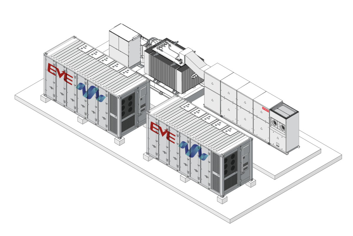
EcoJoule Energy has teamed up with Hitachi Energy, a global leader in electrification, and battery manufacturer EVE Energy to launch a new industry-leading sub-5 MW battery energy storage system (BESS) that will help alleviate network constraints and maximise existing and new consumer energy resources (CER).
EcoSTORE MEGA is engineered for both grid-following and grid-forming applications and integrates EVE Energy’s 5 MWh MR Giant LFP battery containers with Hitachi Energy’s WD4 power conversion system and centralised power plant controller. This architecture enables precise active and reactive power control for utility-scale projects.
The system is built around a standard 4.98 MW/5 MWh block architecture that can support a range of energy durations using a common PCS platform. This modular approach allows developers and utilities to scale capacity over time while maintaining consistent performance across sites.
The modular system has been designed and integrated in Australia to meet the operational, regulatory and environmental requirements of local electricity networks. The system combines Hitachi Energy’s bi-directional power conversion systems and control technology with high-efficiency lithium iron phosphate battery containers from EVE Energy.
The EcoSTORE MEGA will allow network operators to alleviate network constraints on high-voltage feeders and substations, enable more CER connections, and reduce reliance on large-scale generation solutions, which are facing high costs and social challenges.
EcoJoule Energy Founder and CEO Dr Mike Wishart said the partnerships reflected the importance of combining globally proven technology with strong local engineering and integration capability.
“Battery storage is rapidly becoming critical infrastructure for the Australian energy system, and we believe there is a real opportunity to grow in the space between small household batteries and large utility-scale batteries,” he said.
“EcoSTORE MEGA reflects that philosophy and combines proven Tier-1 components with EcoJoule’s deep experience in power electronics, system integration and grid compliance to deliver a reliable and scalable energy storage platform designed specifically for Australian network conditions.”
EcoJoule Chief Commercial Officer Martin van der Linde said EcoJoule Energy’s role as a local integrator was critical to ensuring global battery technology performs effectively within Australia’s complex grid environment.
“Successful battery projects require more than high-quality hardware. They require a deep understanding of local grid behaviour, compliance requirements and network expectations,” Mr van der Linde said.
“As an Australian engineering and integration partner, EcoJoule works closely with developers, utilities and network operators to ensure systems are designed, commissioned and operated to perform in real-world conditions,” he said.
“By integrating global technology locally, we can customise each system for Australian standards and operating environments while providing onshore engineering, commissioning and long-term support.
“With EcoJoule managing the entire engineering and rollout, we can get systems on the ground quickly and efficiently reducing delivery risk for our customers and helping ensure these assets perform reliably over their entire operational life.”
EcoJoule’s other products include:
EcoVAR ALTO is a pole-mounted low voltage STATCOM that regulates voltage levels on distribution networks in real time. The technology enables network operators to integrate more consumer energy resources and electrification technologies without costly grid upgrades.
EcoSTORE ALTO is an intelligent, Australian-made, pole-mounted BESS/STATCOM that improves energy quality, reliability, and efficiency, particularly in fringe-of-grid and renewable-heavy networks.
EcoSTORE MEGA has been designed to meet Australian and international safety and grid compliance standards, including AS/NZS and IEC requirements. The system delivers high efficiency, fast control response and long-term operational reliability in demanding utility environments.
The highly integrated and standardised design simplifies transport, installation, connection and commissioning, while comprehensive deployment and operator training programs support project delivery.
Established nearly a decade ago, EcoJoule Energy is a 100% Australian-owned company providing innovative solutions to help electricity distributors integrate renewable energy and manage grid reliability.
In early 2025, the company secured a $15 million capital investment from Ellerston Capital and the Clean Energy Finance Corporation (CEFC) to support the company’s national and international growth ambitions.
For more information and specifications, visit the EcoSTORE MEGA page.
Media enquiries to: Ben Ready +61 415 743 838 ben@rgcmm.com.au.
Low-voltage planning has long been able to treat a feeder as a balanced three-phase circuit. For most of the network’s history that was a safe assumption. High penetrations of single-phase distributed generation and single-phase load are ending it, and they do so in a way an aggregate check doesn’t catch.
Voltage compliance is assessed per phase. In Australia, the nominal is 230 V with a range of +10% / −6% (AS60038 and AS61000.300.1), and each phase at the point of supply has to sit inside that range, not the average of the three, each one independently.
Single-phase connections are where this bites. A rooftop inverter or an EV charger connects to one phase, not three. At low penetration the connections diversify across phases and across the day, and the feeder behaves close to balanced. At high penetration that diversity fails. PV exports on the phases it happens to sit on through the middle of the day; EV charging loads other phases through the evening. One phase is pushed toward the upper limit at midday while another is dragged toward the lower limit at the evening peak.
The trap is that the three-phase average can look compliant while an individual phase is in breach. A planner working from aggregate feeder loading, or from a balanced load-flow assumption, sees headroom that isn’t there.
This is not only a high-solar story. Any concentration of single-phase power-electronic load does the same thing from the other direction. EV charging, and increasingly induction cooking, draws hard on whatever phase it happens to be wired to. A network with modest rooftop PV but rising electrification will see the same per-phase divergence, driven by load rather than generation. The mechanism is the connection being single-phase, not whether it imports or exports.
The instinct is to reach for conductor augmentation. Larger conductor lowers impedance, and lower impedance does reduce the magnitude of voltage excursions. That part is real. But it reduces them symmetrically. It does nothing about the asymmetry between phases, and nothing about the time-of-day variation that drives the swing. Conductor is a fixed impedance: it cannot pull a phase down at midday and hold it up at the evening peak. To bring a single over-voltage phase back inside the limit by impedance alone, you would oversize the conductor well beyond the thermal load — paying for capacity you don’t need to address a problem conductor was never the right tool for.
Behind-the-meter batteries are sometimes offered as the answer. For a network planner they are not, because they cannot be centrally controlled, and they are also usually a single phase device, doing which does not fix feeder balance. A customer’s battery cannot be dispatched to hold a phase within limits, and it cannot be counted on for compliance.
A STATCOM put in now is not interim spend to be written off when the larger upgrade arrives.
What corrects a per-phase, time-variable problem is per-phase, dynamic control. An LV D-STATCOM regulates each phase independently and continuously: absorbing reactive power on the phase running high, supplying it on the phase running low, and rebalancing load across the three phases. It tracks the daily cycle rather than being tuned to a single condition.
There is a second consequence worth naming. Because a feeder is limited by its worst-loaded phase, unbalance leaves real capacity stranded, two phases can sit well under their limit while the third sets the constraint. Rebalancing recovers that capacity and lets a network use conductor it already owns to its actual rating. That is what defers augmentation, rather than simply delaying it.
None of this replaces augmentation, and augmentation does not replace it. They sit on the feeder as two layers doing two jobs. New conductor adds thermal capacity and lowers impedance; it does not balance phases, filter harmonics, regulate voltage through the day, or report the power-quality conditions where it sits. Those functions do not arrive with copper, and they do not stop being needed once copper is installed. The capacity an upgrade unlocks tends to fill with more of the single-phase load and generation that drove the divergence in the first place.
So a STATCOM put in now is not interim spend to be written off when the larger upgrade arrives. It is the control layer that keeps a feeder balanced and compliant before augmentation, through it, and after it. Where the constraint is genuinely thermal and the conductor cannot carry the current, augmentation is the right answer. The STATCOM stays in service, doing the work the new conductor was never going to do. The two are complementary by design.
The per-phase compliance trap is not a future problem. It is already visible on high-penetration feeders that pass an aggregate check and fail a per-phase one. Worth checking which of yours do.
Why a 40 kVAr device supports voltage on a feeder carrying far more than 40 kVA, and how much correction to expect
A common question from distribution engineers assessing a low voltage D-STATCOM is how a 40 kVAr device can support voltage on a feeder that carries far more than 40 kVA. The question almost always traces to one assumption: that the device sits in series with the feeder and must carry the full load current, the way a line voltage regulator does.
A shunt-connected D-STATCOM does not work that way. It connects in parallel, carries only its own reactive current, and supports voltage through the reactance between its connection point and the source. This note sets out the mechanism and works a representative example.
Series and shunt connection are different problems
A series voltage regulator is installed in line with the feeder. All feeder current passes through it, so it must be rated for the full through-current, often several hundred amps. Measured against that benchmark, 40 kVAr looks too small to matter.
A shunt D-STATCOM connects across the feeder at a single point. Feeder current does not pass through it. The device carries only the current corresponding to its own rating:
I = Q / (√3 × V) = 40,000 / (√3 × 400) ≈ 58 A where Q = 40 kVAr, V = 400 V phase to phase
That 58 A is independent of feeder loading. The device is sized to its own reactive current, not to the feeder it supports.
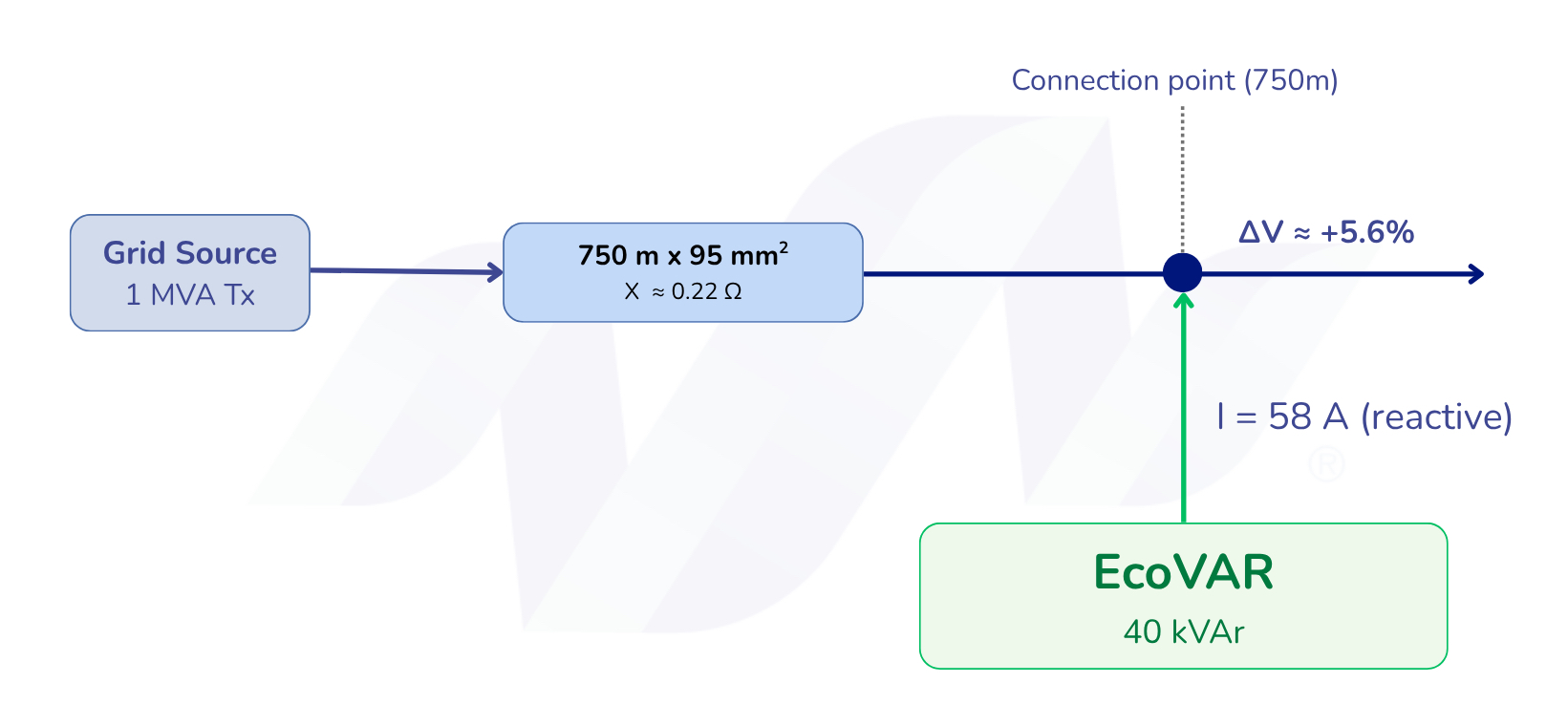
Figure 1. The EcoVAR connects in parallel at the feeder. Feeder load current flows along the line, not through the device. The voltage rise is set by the reactance between the connection point and the source
How reactive injection raises voltage
The network behind any connection point can be represented as a source with a series impedance, R + jX, back to it. Current flowing through that impedance produces a voltage difference. The familiar low voltage drop relationship is:
ΔV ≈ (P·R + Q·X) / V
A shunt D-STATCOM supplies reactive power locally, so that reactive power no longer has to be imported through the upstream reactance X. Removing Q from the upstream path removes the Q·X voltage drop it was causing, and the local voltage rises. For a reactive-only device the support reduces to:
ΔV ≈ Q·X / V
Worked example
Consider a 1 MVA distribution transformer feeding a 1 km low voltage feeder on 95 mm² overhead conductor, with the D-STATCOM connected 750 m along the feeder. Representative values:
Transformer reactance
Xtx ≈ 0.008 Ω
Line reactance to the connection point (0.29 Ω/km × 0.75 km)
≈ 0.218 Ω
Total upstream reactance
X ≈ 0.225 Ω
Applying the relationship:
ΔV ≈ Q·X / V = 40,000 × 0.225 / 400 ≈ 22.5 V ≈ 5.6%
The same result follows from the device current and the upstream reactance, which is worth showing because the two routes are the same physics:
ΔVLL ≈ √3 × I × X = √3 × 58 × 0.225 ≈ 22.5 V
On this feeder, a 40 kVAr device applies about 5.6% voltage correction at its connection point.
It’s important to remember that the STATCOM can both source and sink VARs, so it can move the voltage in either direction, either up or down 22.5V in this simplified case. This allows it to respond to voltage rise from solar, or voltage drop from load, in real time.
The connection point sets the result
The feeder in the example is 1 km long, but the device sits at 750 m. The final 250 m plays no part in the calculation, because the device’s reactive current flows back to the source through the upstream reactance only. Voltage authority is set by the impedance between the device and the source, not by the total feeder length. This is why siting matters: the device belongs where the upstream reactance, and the voltage problem, are greatest. It is also the clearest distinction from a series device, whose effect depends on what lies downstream of it.
Where the relationship applies
The Q·X / V relationship depends on the feeder having meaningful reactance. Overhead open-wire conductor, with an X/R ratio near 1, meets that condition. On low-reactance cable the same kVAr produces little voltage movement, and a D-STATCOM earns its place through phase balancing rather than bulk reactive support.
It is also worth separating the correction the device applies from the total feeder voltage drop. On a feeder with X/R near 1, the real-power drop (P·R) from load current is comparable to the reactive drop, and a reactive device does not act on it. The 5.6% figure is the correction available at the connection point, not the elimination of the feeder’s full drop under load.
In practice. A shunt D-STATCOM provides voltage correction at the point where it is needed, sized to its own reactive current rather than to feeder loading. The EcoVAR adds two capabilities relevant to low voltage feeders: independent phase balancing, which addresses the per-phase voltage problem that symmetric reactive injection cannot, and installation without a feeder outage. On a weak overhead feeder these allow voltage to be corrected at the connection point in place of, or ahead of, conductor augmentation.