Australian energy technology company EcoJoule Energy has secured a Grid Enhancing Technologies Grant (GET) Program to support the deployment of its innovative technology that improves the efficiency and capacity of Australia’s electricity networks.
EcoJoule Energy is one of 14 successful grant recipients announced by Minister for Climate Change and Energy Chris Bowen as part of a $30 million investment in projects designed to create a smarter, more efficient and resilient electricity system.
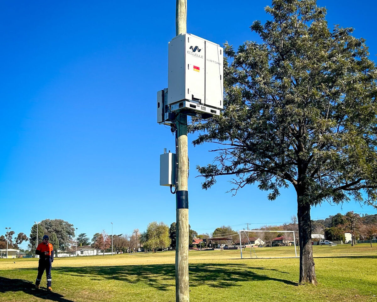
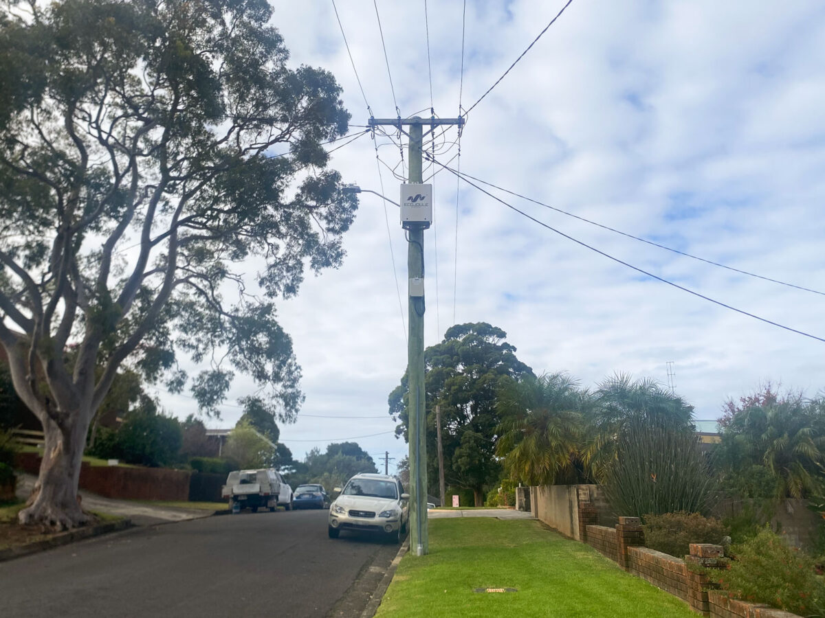
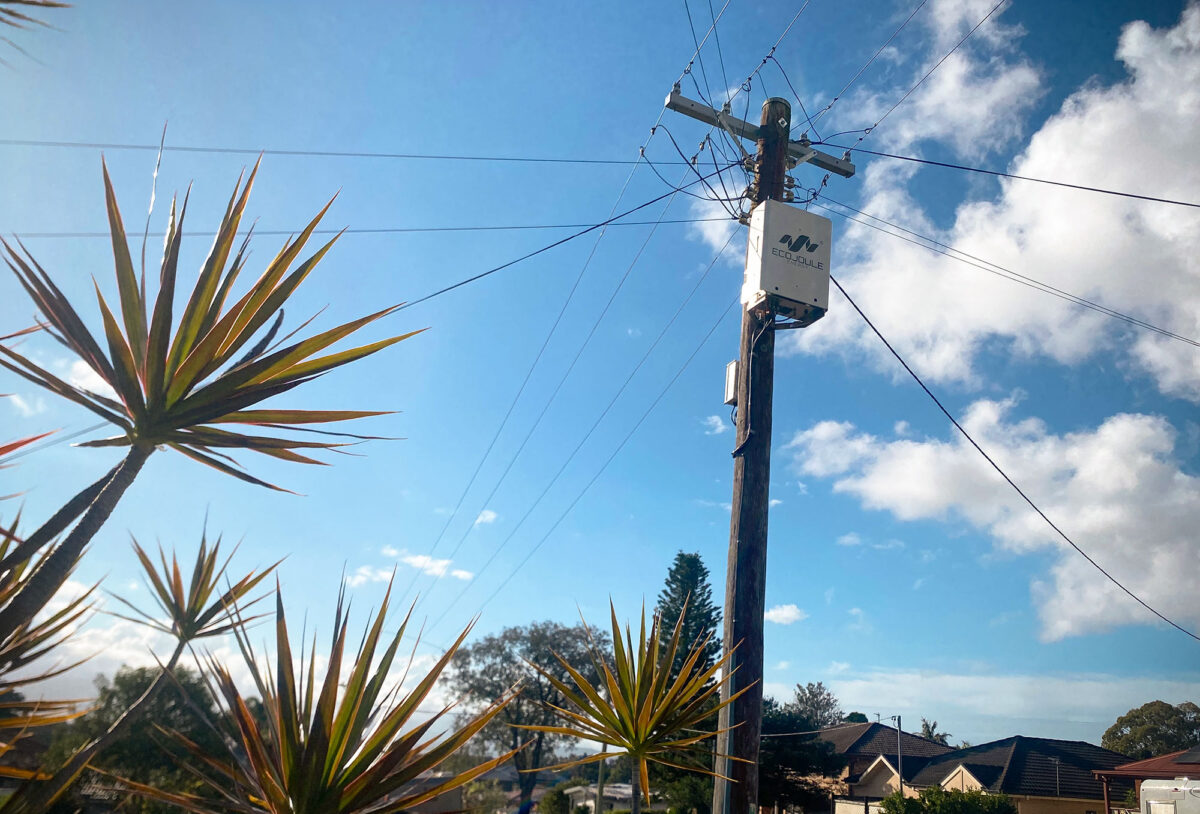
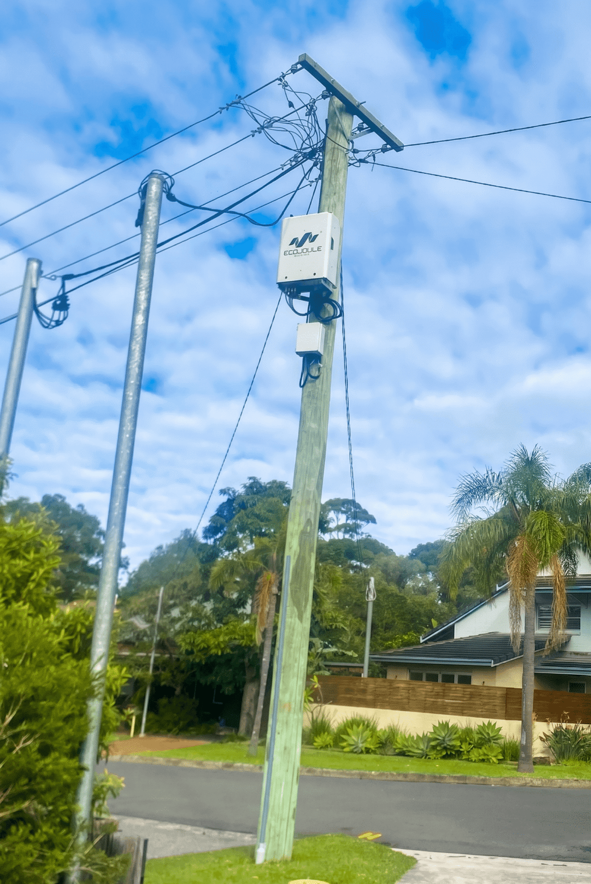
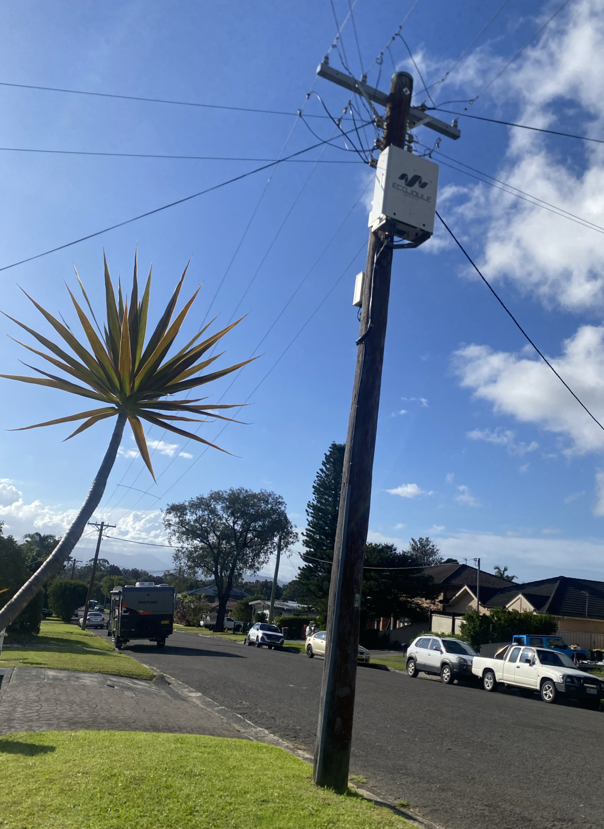
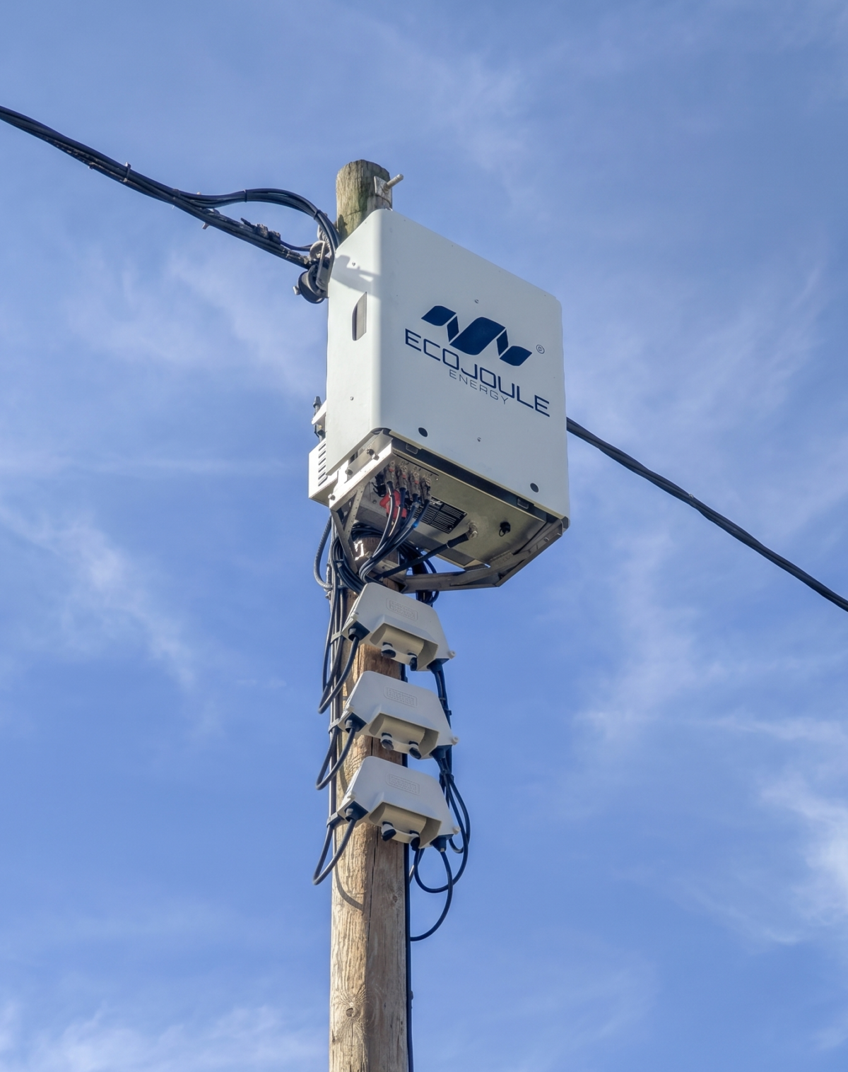
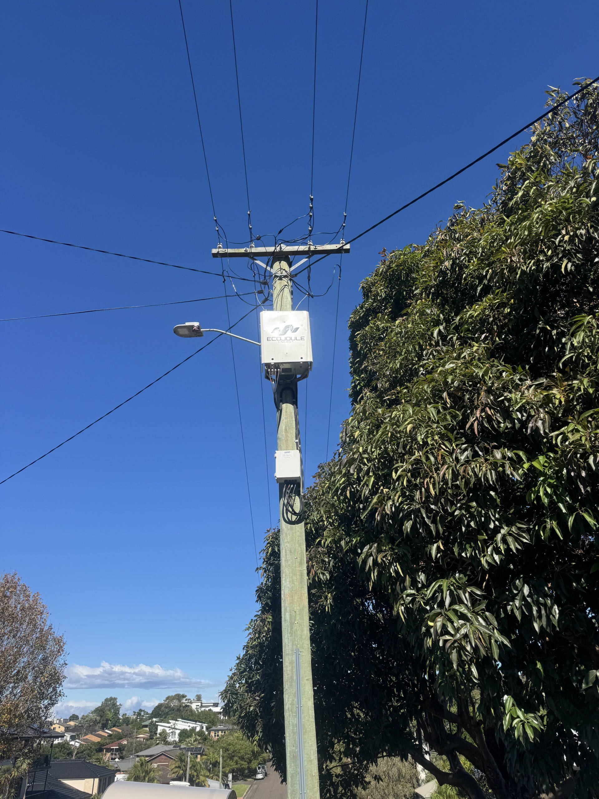
The funding will support EcoJoule Energy to demonstrate how advanced network optimisation technologies, including the EcoVAR Alto and the EcoSTORE Alto, can help electricity distribution networks manage voltage, increase their capacity to accommodate renewable energy and make better use of existing infrastructure.
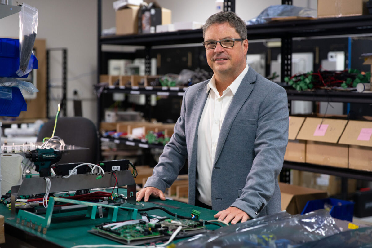
EcoJoule Energy CEO Dr Mike Wishart welcomed the grant and thanked the Australian Government for supporting the continued development and deployment of Australian-developed and Australian-made grid technology.
“We welcome the Australian Government’s investment in Grid Enhancing Technologies and thank Minister Bowen and the Department of Climate Change, Energy, the Environment and Water for their support,” Dr Wishart said.
“Australia’s energy system is undergoing a fundamental transformation as rooftop solar, batteries, electric vehicles and other distributed energy resources become a larger part of the energy mix,” Dr Wishart said.
“This transition is creating new challenges for electricity networks, particularly at the low-voltage level. It is also creating an opportunity to use smart, flexible technologies to get more from the infrastructure we already have.
")
EcoJoule Energy develops and manufactures advanced power quality and battery energy storage systems for distribution electricity networks in Australia and international markets. The company’s technology is currently in use in nearly a dozen countries on four continents.
The technology helps network operators manage voltage, improve power quality and accommodate growing levels of customer energy resources (CER).
Dr Wishart said the GET Grant Program recognised the important role Australian innovation would play in modernising the nation’s electricity grid.
“Australia is a global leader in the adoption of rooftop solar, but realising its full value will require greater investment in the distribution networks that connect homes and businesses,” he said.
“Network optimisation technologies can address voltage constraints and release additional capacity without relying solely on major new infrastructure.
“This project will provide valuable evidence about how these technologies can be deployed more broadly to benefit networks, consumers and the wider energy system.
“EcoJoule is proud to be contributing Australian-developed technology and expertise to this important national program.”
The GET Grant Program forms part of the Australian Government’s Rewiring the Nation program. The 14 successful projects will operate across Queensland, New South Wales, Victoria, Western Australia, South Australia and the Australian Capital Territory.