Volt-VAR Droop and Active Power Balancing in the EcoVAR LV STATCOM

How the two simultaneous control loops in a three-phase LV STATCOM work, and what each one can and cannot correct.

1. Summary

  • The EcoVAR uses three independently controlled single-phase inverter stages connected to one shared DC bus.
  • A Volt-VAR droop curve sets reactive power as a function of measured voltage. The EcoVAR evaluates that curve against each phase voltage separately, so one phase can absorb VArs while another injects them.
  • A second loop, Active Power Balancing, runs at the same time. It moves real power from lightly loaded phases to heavily loaded phases through the shared DC bus.
  • The two loops correct different things. Reactive power shifts each voltage as well as the average voltage; active power transfer corrects the difference between phases and reduces neutral current. Neither substitutes for the other.
  • Both loops operate from voltage measurement only. No series current transformers are required, so installation does not depend on breaking the conductor.

2. What a Volt-VAR droop curve does

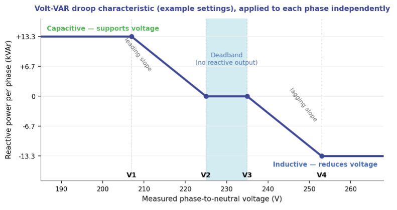
A Volt-VAR droop curve is a piecewise-linear rule that converts a measured voltage into a reactive power command. It is defined by four voltage set points and applied continuously, without operator intervention or a network communications link.

Below the lower set point the STATCOM sources reactive power (capacitive operation), which raises voltage at the point of connection. Above the upper set point it sinks reactive power (inductive operation), which lowers voltage. Between the two inner set points the output is zero. That deadband stops the unit from responding to normal small voltage variations.

The EcoVAR follows the generator sign convention: a positive reactive power reference is capacitive (sourcing VArs), a negative reference is inductive (sinking VArs). The characteristic is as described in AS/NZS 4777.2:2020 and similar international standards like EN50549, with leading and lagging slopes that can be set symmetrically or asymmetrically.

Figure 1 — Volt-VAR droop characteristic. Set points shown are an example only.

3. Configurable set points

All four set points are user-configurable from the EcoVIEW engineering tool or by uploading a settings file through EcoFLEET Manager. A limited set is also available over DNP3 and Modbus.

Set pointRangeFunction
V1180 – 225 VAt and below V1 the phase holds maximum capacitive output.
V2185 – 250 VLower edge of the deadband. Capacitive output falls linearly from V1 to zero at V2.
V3185 – 260 VUpper edge of the deadband. Inductive output starts here.
V4190 – 277 VAt and above V4 the phase holds maximum inductive output.

Rated output is 40 kVAr total, 13.33 kVAr per phase, available in both directions across 210 V to 277 V. The unit continues to operate down to 180 V at a maximum continuous 63.5 A per phase, and tolerates connection to any voltage from 0 V to 280 V without damage.

4. Three inverter stages, one DC bus

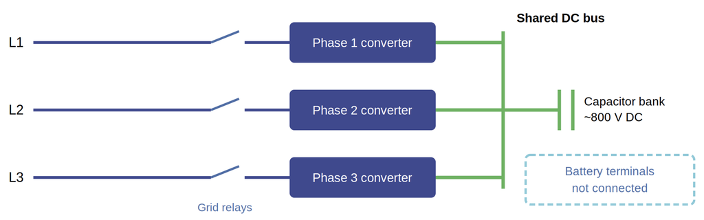
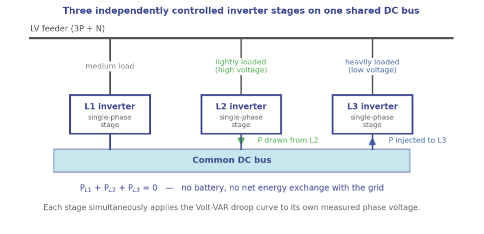
The EcoVAR is not a single three-phase bridge producing a balanced output. Each phase is served by an inverter stage with its own current control loop, and all three stages are connected to a common DC bus. Two consequences follow directly from that architecture.

First, each stage can be commanded independently. The droop curve is evaluated three times each control cycle, once per phase, against that phase’s own measured phase-to-neutral voltage. One phase reaching its current limit does not constrain the other two.

Second, active (real) power can be moved between phases. Because the three stages share a DC bus, power drawn from one phase can be injected into another without a battery and without any net exchange of energy with the network.

Figure 2 — Active power transfer between phases through the shared DC bus.

5.  A single characteristic, three independent evaluations

The three phases share one droop characteristic — the same four set points and the same slopes apply to all of them. What is independent is the input and the output, not the configuration. Each stage measures its own phase voltage and produces its own reactive power command from the shared curve.

This is what allows the EcoVAR to reduce voltage unbalance rather than simply shift the whole voltage profile. On a feeder where L1 sits at 252 V under high PV export and L3 sits at 228 V under load, the same curve puts L1 into full inductive operation and L3 into capacitive operation at the same instant.

The unit can alternatively be configured to act on the average of the three phase voltages. That mode is available for networks whose standards require it, but it gives a poorer voltage outcome for customers and is not the recommended setting.

6.  The second loop: Active Power Balancing

Reactive power alone corrects voltage well on reactive networks. On resistive LV networks — underground cable, long aluminium mains, heavily loaded urban feeders — voltage responds more strongly to real power than to reactive power, and reactive injection alone cannot bring the phases together.

Active Power Balancing addresses this. The EcoVAR takes the three phase voltages as a proxy for phase loading: a higher voltage implies a lighter load, a lower voltage implies a heavier one. It then transfers real power from the lighter phases to the heavier ones in proportion to the voltage differences, subject to the constraint that the three phase powers must sum to zero. This reduces current unbalance on the feeder and neutral current at the transformer.

Using voltage as the proxy avoids series current transformers. That removes both the cost and the outage that a CT installation would otherwise require.

Two modes are provided. Gain-based transfer injects real power per phase in proportion to the deviation from the average voltage, with a user-selected P or Q priority that determines which is curtailed first if a phase reaches its apparent power limit. Optimal X/R computes a reference apparent power per phase from a voltage droop and then splits it into active and reactive components according to the source impedance X/R ratio, which is taken from the network model or estimated at commissioning. Active Power Balancing is disabled by default and is enabled per site.

7.  Why both loops are needed

The two loops are subject to different constraints, and that is the whole reason for running them together.

 Volt-VAR droop (Q)Active power balancing (P)
Quantity controlledReactive power per phaseActive power transfer between phases
Network constraintLimited only by the per phase apparent power rating of the unitSum of the three phase powers must be zero
Effect on average voltageCan raise or lower all three phases togetherNone — the three voltage changes sum to zero
Effect on unbalanceReduces it, most effectively on reactive networksReduces it, most effectively on resistive networks
Effect on neutral currentIndirectDirect reduction at the transformer
Default stateEnabledDisabled — enabled per site

If all three phase voltages are high, transferring real power between them cannot bring any of them down, because whatever one phase gains another must lose. Only reactive power can move the average. Conversely, on a resistive feeder with one badly loaded phase, reactive power struggles to close the gap and real power transfer does it efficiently. Running both loops covers both cases across the full range of LV network impedances.

8.  Control loop timing

FunctionResponse
Internal current control loop10 – 90% rise and fall in 2 ms or less
Volt-VAR droop response (ramp-rate limited)Default 5 s, to keep the steady-state response smooth. However, can be set sub-cycle for fast response, typically when Active Power Balancing is disabled.
Voltage sag and swell limiting10 ms time constant; overrides the droop response
Reactive current overshootNo more than 5% of steady-state output

The current loop is fast enough to respond within a tenth of a cycle. The droop response is deliberately slowed to five seconds so that the unit regulates steady-state voltage rather than chasing transients. Fast events are handled separately: if a phase reaches 180 V or 277 V, the sag and swell function commands maximum reactive power with a 10 ms time constant and overrides the droop.

9.  What to specify at commissioning

  • Four droop set points, plus symmetrical or asymmetrical slopes.
  • Per-phase control enabled, or average-voltage mode if a network standard requires it.
  • Active Power Balancing: disabled, gain-based, or optimal X/R.
  • For gain-based operation: P priority or Q priority, chosen from the local X/R ratio — Q priority for overhead and other reactive feeders, P priority for cable and other resistive feeders.
  • For optimal X/R operation: the X/R ratio, from the network model or estimated during commissioning.

For settings files, network studies or a copy of the EcoVAR ALTO user manual, contact EcoJoule Energy at sales@ecojoule.com or your regional distributor.  

Why D-STATCOMs deliver faster fixes for Low Voltage Network Power Quality

A D-STATCOM (Distribution LV STATCOM) and a feeder augmentation can both bring an LV feeder back inside voltage limits. They differ in how much engineering, land access and switching work sits between identifying the problem and the network being compliant. Four reasons the D-STATCOM path is shorter.

1. A D-STATCOM uses the existing poles and wires

An augmentation project changes the network’s physical assets. That means a feeder civil design: pole loading and strength assessment, conductor selection, clearance checks, possible easement or land acquisition for a new substation site, and design approval before any works order issues.

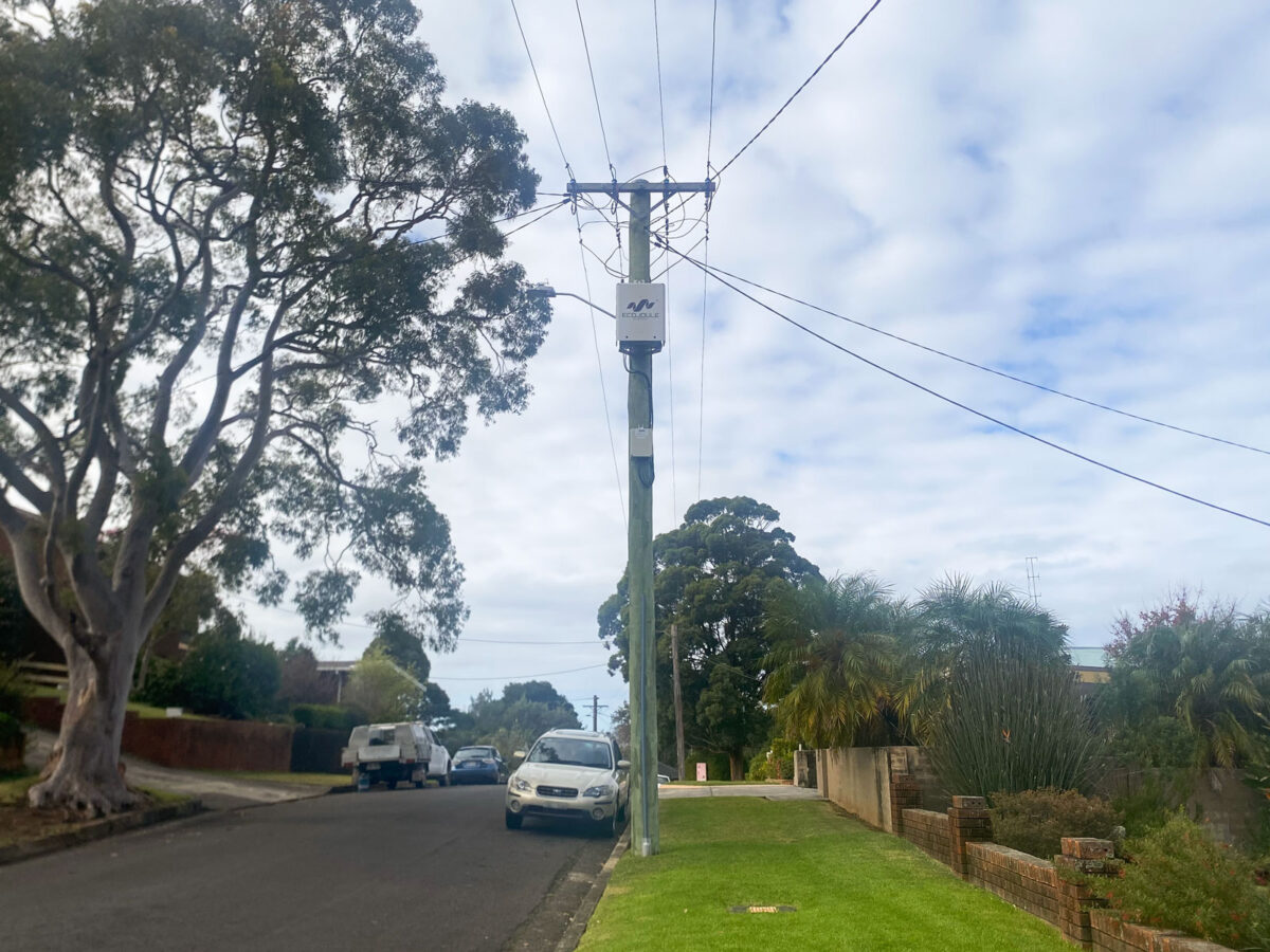
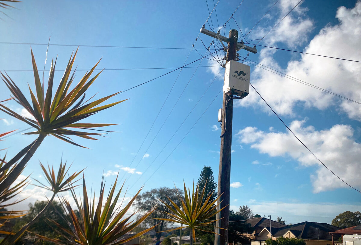
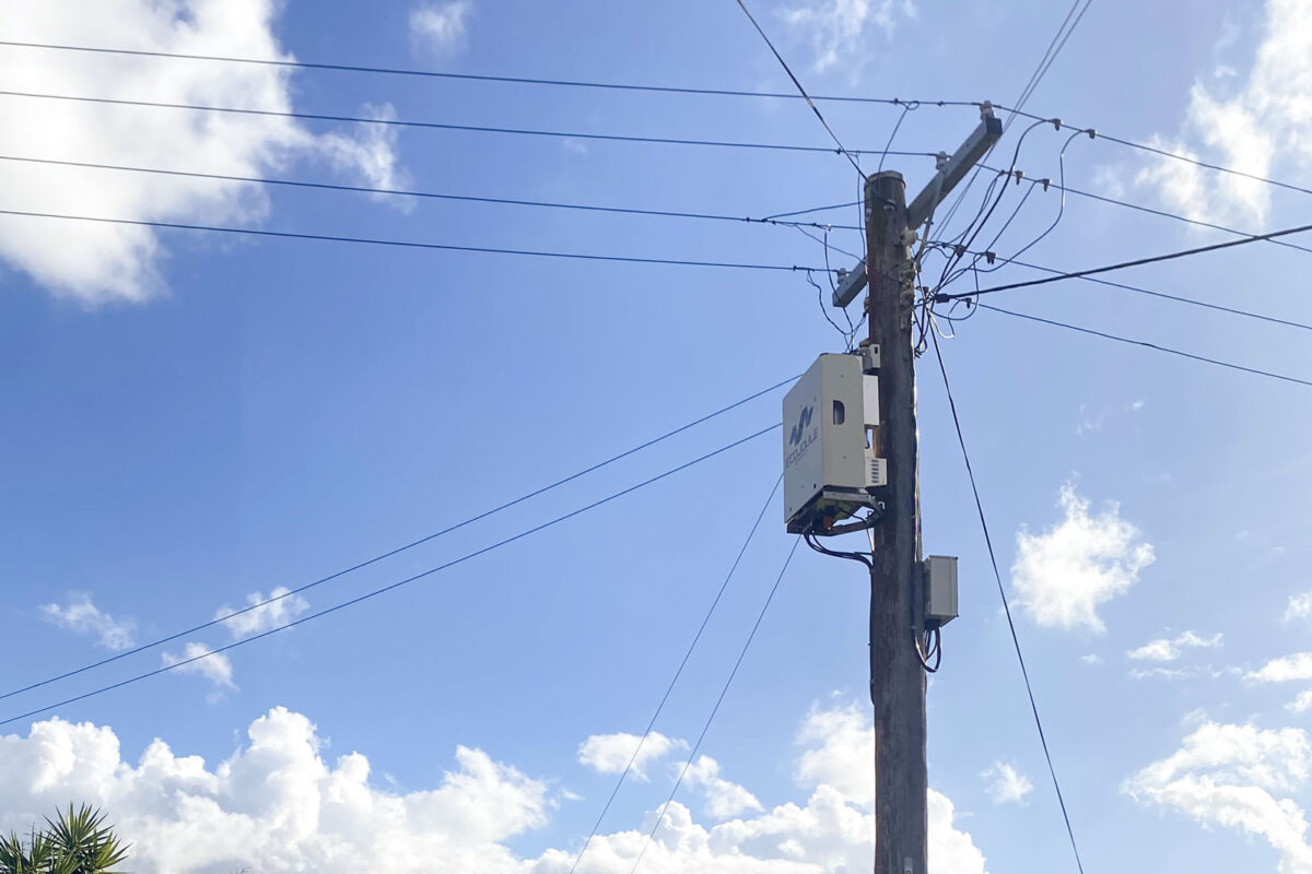
A D-STATCOM changes the network’s electrical behaviour without changing its topology. The EcoVAR Alto mounts on an existing pole; the EcoVAR Terra sits on a pad. Both connect to the existing LV mains. No conductor replacement, no new feeder route, no land acquisition. The civil design and land access critical path is removed, not shortened.

2. D-STATCOMs connect in parallel, not in series

A series device sits in the supply path. Installing it requires an LV outage, customer notification and a switching programme, and once installed it becomes a single point of failure between the transformer and the customer.

A D-STATCOM connects in parallel through its own protection. Consequences for delivery:

  • Installation is a live connection — no planned outage, no notification process, no switching programme.
  • An internal device fault operates the device’s protection and disconnects the unit. Supply to customers is unaffected; the network returns to its pre-installation condition.
  • No new customer-interruption failure mode is introduced into the supply path, so the reliability case is straightforward.

3. One construction design per LV line type, used network-wide

The D-STATCOM installation is feeder-agnostic. The arrangement depends on the line construction, not on the feeder’s loading, length or fault level.

In practice, standards teams develop one standard arrangement per LV construction type in their network — bare conductor, aerial bundled conductor, underground pad-mount — and then apply it everywhere. Design effort becomes a one-off standards exercise rather than a per-project one. Once the standard arrangement exists, each subsequent site is a works order, not a design job.

4. The settings are generally common to every site but can be easily modified if required

The EcoVAR combines two control systems in one unit:

  • Volt-VAR reactive control for voltage regulation and power factor.
  • Simultaneous active power balancing control (patented) that transfers real power between phases to correct imbalance and neutral current.

Both controls act in closed loop on conditions measured at the point of connection. They are generally not tuned to a modelled feeder, so the setting file does not change site to site. One approved setting file covers the network. On occasions, for unusual sites (eg. Excessively weak low voltage feeders) the settings can be easily remotely modified.

That has direct operational consequences: spares are interchangeable across the fleet, a hot swap needs no re-engineering, and a crew can redeploy a unit from one site to another without a new study.

The net effect

The first D-STATCOM deployment carries the standards work: one arrangement per line type, one approved setting file. Every deployment after that is procurement plus a works order. Augmentation repeats the design, approval and outage cycle at every site.

Next step: EcoJoule can provide sample GA drawings for EcoVAR D-STATCOM installations, together with standard configuration for the Volt-VAR Droop curve. Contact EcoJoule for more information.

Why add remote communications to your LV STATCOMs

What a connected EcoVAR gives a distribution utility, and how the connection is made.

Most utilities can describe the state of their HV and MV networks in near real time. Below the distribution transformer, the picture thins out. Smart meters report at the point of supply, usually on 15 or 30 minute intervals, and they tell you what a customer connection looked like, not what the feeder was doing between the readings.

An LV STATCOM sits in that gap. It is already measuring the LV feeder continuously, because it has to: voltage, current and harmonic content on each phase are the inputs to its control loop. Whether that measurement stays inside the unit or reaches your planning and operations teams is a decision made at installation, and it costs very little to make the right one.

This article sets out three reasons to connect your LV STATCOMs, and then the practical detail of how it is done on the EcoVAR.

1. Visibility of the LV network

A connected EcoVAR reports three classes of data that most utilities have never held for the LV network at scale.

Voltage. Per phase voltage, as well as STATCOM current, active and reactive power, at the point of installation, at a resolution well beyond metering intervals. Because the EcoVAR is typically installed at the electrical problem, at the end of a long feeder or on a section with heavy solar export, the data comes from the location where your planning assumptions are least reliable. Phase by phase reporting also quantifies imbalance directly, rather than inferring it from connection records that may be decades out of date.

Harmonics. Individual harmonic orders and total distortion, per phase, over time. Harmonic distortion on LV networks is rising with inverter based generation, EV charging and switched mode loads, and most utilities have no ongoing measurement of it. Connected EcoVARs give you a distortion baseline for the sections where you have units installed, and a time series that shows when distortion is worst and how it correlates with load and generation.

Oscillography. Triggered waveform captures around events: voltage dips, transients, and protection operations. This is the class of data that separates a monitoring device from a meter. When a customer reports flicker or equipment damage, a waveform capture from the LV feeder gives an engineer something to analyse rather than something to guess at.

None of this displaces smart metering. It complements it. Smart meters tell you about load profile and customer experience at the connection point. A connected STATCOM tells you about the behaviour of the feeder itself, including reactive power flow and distortion that metering does not report.

The data is available for export into network modelling, digital twin and visualisation platforms. Measured LV voltage and harmonic profiles improve the calibration of LV models that are otherwise built on assumed diversity factors and nominal impedances. For utilities running LV network visibility programmes, connected STATCOMs are an additional measurement layer at sites you were already investing in.

2. Remote adjustment of setpoints and droop curves

An EcoVAR is commissioned with a voltage setpoint and a droop characteristic that suit the feeder as it is understood on the day. Feeders change. Solar penetration increases, EV charging arrives, load transfers occur, and seasonal load composition shifts.

With communications in place, setpoints and droop curves are changed from the office. Without them, every settings change is a truck.

Conservation Voltage Reduction

Conservation Voltage Reduction (CVR) is the deliberate operation of the distribution network toward the lower end of the permitted voltage range in order to reduce energy consumption and peak demand. It works because a meaningful share of connected load is voltage dependent. Resistive heating, some lighting, motors and transformer no load losses all draw less power at lower voltage, and lower voltage also reduces network losses.

The metric used to quantify the effect is the CVR factor: the percentage reduction in demand or energy per one percent reduction in voltage. Published studies commonly report values of about 0.5 to 1.0 for active energy, with higher factors for reactive power and seasonal variation depending on load composition. Utility programmes typically report energy savings in the range of 1 to 4 per cent, achieved without any action by customers.

The constraint on CVR is the low point. A utility can only lower voltage until the worst served customer on the worst feeder reaches the statutory minimum. Everything above that point is headroom the utility cannot use.

This is where LV reactive support and CVR intersect. An EcoVAR clamps the voltage at the new setpoint on the network, controlling the voltage down the LV feeder, not simply at the transformer.

Communications make that relationship manageable. As a CVR programme is tuned, the target voltages at the LV support points need to move with it, seasonally and as the network changes. Doing that remotely across a fleet is straightforward. Doing it with field visits is not.

3. Condition monitoring and evidence led maintenance

The EcoVAR requires no scheduled maintenance. There are no filters to change, no fans to service and no consumables. Stated plainly, that means a time based maintenance programme adds cost without adding reliability.

The alternative is to attend site when the equipment tells you to. A connected fleet reports internal temperatures, converter status, alarm and event history, availability, and the reactive power the unit is actually delivering against what the network is asking of it. That supports three decisions a maintenance planner needs to make:

  • Which units, if any, need attention.
  • Whether a reported network problem is the STATCOM or the network.
  • Whether units are correctly sized and set for the feeders they are on, or whether some are running at their limits while others are barely working.

The third point tends to be the one that changes budgets. Fleet data shows where a unit is under utilised and could be redeployed, and where a feeder has outgrown the support installed on it.

There is a fair objection here. If the equipment is maintenance free, why monitor it? Because maintenance free is a statement about scheduled intervention, not a claim that nothing will ever need attention. Monitoring is what lets you replace a calendar with evidence, and it is also what lets you prove availability to your own asset management function.

How to add communications to an EcoVAR

Physical provisions

Every EcoVAR provides:

  • An RJ45 Ethernet data port for the communications device.
  • A DC auxiliary supply, nominally 15 V, 15 W, for powering that device.

The utility selects the communications bearer. In practice this is usually a cellular router where no utility network exists at the site, or a connection into an existing utility WAN, fibre or mesh where one does. Because the EcoVAR supplies the router, no separate supply, meter or service connection is required. The communications device is powered from the asset it is monitoring.

Three communications paths

PathWhat it delivers
DNP3Integration into conventional SCADA and ADMS platforms. LV measurements and status appear in the system your control room already uses, extending SCADA visibility down to individual LV feeders.
ModbusThe same SCADA integration for utilities and RTUs standardised on Modbus. For utilities with mature SCADA and established cyber processes, DNP3 or Modbus is usually the path of least resistance.
Secure APIConnects the unit to EcoFLEET, the EcoJoule fleet management and configuration platform. EcoFLEET aggregates field performance data across the fleet, provides real time dashboards, and handles remote firmware and settings updates.

EcoFLEET is normally hosted within the utility environment, under the utility security controls. EcoJoule can host it for utilities that want an additional service layer, and that arrangement is agreed case by case.

The paths are not mutually exclusive. A common arrangement is DNP3 or Modbus into SCADA for operational monitoring and control, with the Secure API to EcoFLEET for engineering data, fleet analytics and firmware management.

What the data lets you find

Connected LV STATCOMs turn a class of LV faults from customer reported into utility detected:

  • Harmonic sources. Distortion measured at multiple points identifies which section a source sits on.
  • Blown LV fuses and open neutrals. These appear immediately as a phase level anomaly.
  • Voltage excursions and flicker. With waveform evidence attached, rather than a description over the phone.

Historically the first indication of most of these was a customer complaint, which means the problem had already persisted long enough for someone to be affected by it, and long enough for the evidence to be gone by the time a crew arrived. A connected EcoVAR reports the condition when it occurs.

The commercial case in one line

The hardware provision is already in the unit. The incremental cost of connecting an EcoVAR is a communications device and its data plan. What you get in return is a settings change that costs nothing instead of a truck, LV data you have not previously been able to buy at this resolution, and a maintenance programme driven by condition rather than calendar.

If you have EcoVARs in service without communications, we can scope the retrofit against your existing units. If you are planning a deployment, the time to specify the communications path is now, while the installation is still on paper.

References on Conservation Voltage Reduction

  • US EPA / ENERGY STAR, Voltage Optimisation and CVR: Evaluation, Measurement and Verification Best Practice.
  • Diaz-Aguilo et al., Field Validated Load Model for the Analysis of CVR in Distribution Secondary Networks, IEEE Transactions on Power Delivery.
  • Padullaparti et al., Conservation Voltage Reduction with DERMS, Grid Edge and Legacy Devices, NREL, 2023.
  • Assessment of Conservation Voltage Reduction in Distribution Networks with Voltage Regulating Distribution Transformers, Energies 16(7), 2023.
  • Estimation of Conservation Voltage Reduction Factors Using Measurement Data of the KEPCO System, Energies 10(12), 2017.

The LV D-STATCOM as a Permanent Network Asset

Phase balancing and harmonic mitigation before, during and after augmentation

Summary

Low voltage augmentation adds capacity and lowers impedance. It does not redistribute load between phases, and it does not remove harmonic current from the network. Both problems are growing on distribution networks for the same reason augmentation is being triggered in the first place: single-phase rooftop PV, single-phase EV charging, and inverter-connected load.

An LV D-STATCOM should therefore be specified as a permanent network asset. It performs two functions, continuous phase balancing and active harmonic filtering. No passive augmentation performs this at any cost, and the drivers behind both intensify as a feeder’s load and inverter population grow. Deployed early, it releases capacity from conductors and transformers that are already in the ground. After augmentation eventually proceeds for thermal reasons, it continues to manage the conditions the augmentation was never able to address.

This release sets out the engineering behind that position.

1.  Augmentation changes impedance, not composition

Conventional LV remediation works through impedance. Reconductoring increases conductor cross-section. A larger distribution transformer presents a lower source impedance. Splitting a feeder or adding a substation shortens the electrical distance to the worst-served customer. In each case the voltage consequence of a given current is reduced.

Phase imbalance is not a function of impedance. It is a function of how load and generation are distributed across the three phases, and of how that distribution varies through the day. Connection schedules are balanced at design. Real-time loading is not. Diversity between customers, uneven single-phase PV, and the arrival of 7 kW single-phase EV chargers all produce unequal phase currents on a nominally balanced feeder.

Augmentation attenuates the symptom. The neutral current that flows because of unequal phase loading is unchanged by a larger conductor; the voltage difference it produces between phases is reduced, in proportion to the impedance reduction achieved. Where the imbalance is severe, that reduction may not be sufficient. Where load subsequently grows — and augmentation is generally triggered by load growth — the voltage consequence returns.

An LV D-STATCOM addresses the current, not the voltage drop it produces. The EcoVAR transfers real power between phases through its DC link, drawing from the lightly loaded phases and supplying the heavily loaded one. The phase currents seen upstream of the point of connection are equalised. This is a continuous, closed-loop function that follows the load pattern through the day. No passive asset can do this.

2.  Hosting capacity is set by the worst phase, not the average

Where single-phase PV is unevenly distributed, the normal case, since installation follows customer decisions rather than network planning, the constraining phase reaches the upper statutory voltage limit while the other two retain headroom. Under AS 4777.2, inverters on the constrained phase respond with volt-watt curtailment. Export is lost on one phase while capacity sits unused on the others.

Augmentation raises hosting capacity uniformly across all three phases. It does not correct the asymmetry, so the worst phase remains the binding constraint. The headroom already present on the other phases stays inaccessible.

Phase balancing recovers that headroom. By equalising the phase currents, the voltage rise is shared rather than concentrated, and the curtailment threshold on the worst phase is pushed back. The gain is available from the existing conductor, at the existing rating, without an outage.

This is the more significant point for a network with a mature rooftop PV population: the constraint is frequently distributional rather than absolute. Solving it distributionally releases capacity the utility has already paid for, and returns the benefit to every customer on the feeder rather than to those who happen to sit on the favourable phase.

3.  Harmonic current is not removed by a larger conductor

Harmonic current injection on LV feeders is increasing from PV inverters, EV chargers, variable speed drives, switched-mode power supplies and LED lighting. The resulting voltage distortion is the product of the injected harmonic current and the network’s harmonic impedance at each order.

Lowering the source impedance through augmentation does reduce harmonic voltage distortion at the point of measurement, for a given injected current. That is a real benefit and worth stating plainly. It does not resolve the problem, for three reasons.

The current still flows.  A lower impedance path means harmonic current propagates further upstream, through the distribution transformer and toward the MV network, rather than being attenuated locally. The distortion is relocated rather than removed.

Transformers still carry it.  A replacement transformer carries the same harmonic load current and is subject to the same additional eddy current and stray losses. Thermal derating for harmonic content applies to the new asset as it did to the old one.

An active harmonic filter operates on the current directly. The EcoVAR measures the harmonic content at the point of connection and injects compensating current in counter-phase, so the distorted current is cancelled locally and does not propagate upstream. This function is independent of network impedance, and therefore unaffected by whether augmentation has been carried out. Its 864 V DC link provides the voltage headroom needed to slew injection current fast enough to track higher-order components, and to retain full capability at the top of the statutory voltage range.

4.  Deployment: same day, no outage, utility-controlled

The operational profile is as important to the case as the electrical performance, because it is where the contrast with augmentation is widest.

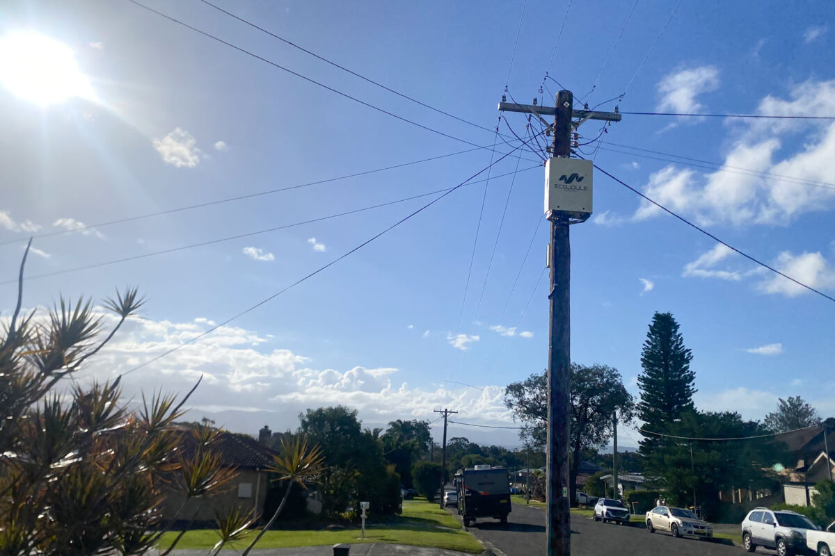
The EcoVAR is pole-mounted and connects in parallel through a set of LV fuses. Installation is carried out live. No customer outage is required, no switching programme, no civil work, no customer notification cycle. A crew installs and commissions in a single visit, on the same day the unit arrives on site.

Once energised, the unit is the utility’s asset in every operational sense. It logs phase voltages, currents, neutral current and harmonic content continuously. Settings are adjusted and firmware updated remotely, by the utility, without a site visit. There is no dependency on the manufacturer for routine operation, and no scheduled maintenance to programme.

Set against an augmentation that requires design, approval, procurement, outage planning and construction — and a capital cost one to two orders of magnitude higher — the D-STATCOM is a decision that can be made and executed inside the time it takes to scope the alternative.

5.  Sequencing across the feeder’s life

The functions above suggest an order of works rather than a choice between alternatives.

Deploy on the existing network.  Where a feeder shows voltage excursions with a significant imbalance component, an EcoVAR increases the usable capacity of the conductors and transformer already installed. Endeavour Energy and Ausgrid crews are completing installations in under two hours. Voltage complaints and PV curtailment are addressed on a timescale of weeks.

Augment when the constraint is genuinely thermal.  Load growth eventually consumes the headroom that balancing releases. When the limit is the current-carrying capacity of the conductor or the rating of the transformer, augmentation is the correct answer and a D-STATCOM is not a substitute for it.

The D-STATCOM continues.  At this point the feeder carries more load, more PV and more inverter-connected equipment than when the unit was installed. The imbalance and harmonic drivers are stronger, not weaker. The EcoVAR continues to perform phase balancing and active harmonic filtering — the two functions the augmentation did not deliver — on a network that now needs them more. It also continues to log at that point, which for most utilities represents a rare permanent measurement location in the LV network.

The unit’s role broadens over the life of the feeder: constraint relief first, then power quality management and network visibility. It is specified once and it stays.

6.  Understanding Siting of the EcoVAR

Siting is not among the constraints, and a few spans either side of the worst-served customer makes little practical difference. The unit does not warrant a detailed siting study. Given the STATCOM exploits upstream impedance, most installations range between halfway and ¾ of the way down an LV feeder. On a cost effective asset such as the EcoVAR, displacing works that cost orders of magnitude more, engineering effort spent optimising position is effort spent for no return. More detail on site selection is covered here: Site Selection for the EcoVAR D-STATCOM: Optimising Placement 

7.  Identifying a candidate feeder

The indicators are measurable and most utilities already hold the data. This is a screening exercise of minutes, not a study:

  1. Voltage excursions on the feeder. If it’s 3 phase excursions, the STATCOMs reactive compensation manages it. Imbalance is managed by the combination of Reactive and Active Power Transfer
  2. Uneven single-phase PV and EV Charger distribution across phases
  3. Rising voltage total harmonic distortion, or customer equipment complaints without a corresponding thermal constraint

Where any of these indicators are present, a single unit on a live feeder produces measured before-and-after evidence from the utility’s own network within weeks — at a fraction of the augmentation cost, and with no outage required to obtain it.

EcoJoule Energy designs and manufactures the EcoVAR LV D-STATCOM in Brisbane, Australia.

Specifying distributed storage for an unbalanced grid: Four things that matter

Four criteria that determine whether distributed storage holds up in a low-voltage network that is no longer balanced.

The low-voltage network is no longer balanced, and it is not returning to a balanced state. Single-phase rooftop solar, single-phase EV charging and uneven load growth mean that voltage imbalance across the three phases is now the normal operating condition on most feeders.

This has a consequence for distributed storage that is often overlooked in procurement. The reliability of a distributed battery is not only a question of cell chemistry or warranty terms. It is a question of whether the asset keeps delivering in the network as it actually is, whether it avoids the failure modes that take enclosed batteries offline, whether it can be restored quickly when it needs service, and whether the operator retains control of it once it is connected.

Those four criteria are where a specification for distributed storage should focus.

Correcting the network the asset operates in

Modern networks are being driven towards unbalance. The prevalence of high power single phase generation and loads – such as PV or EV charging – introduce unbalance that interferes with 3 phase inverters that lack STATCOM capabilities.

In an unbalanced feeder, the modern utility grade BESS with STATCOM capabilities regulate each phase independently, absorbing or injecting reactive current per phase to bring phase voltages back within limits, and it maintains that correction continuously while it charges or discharges real power. It creates its own voltage headroom, then uses it.

A conventional three-phase BESS injects balanced current across all three phases. Where the feeder is already unbalanced, or sitting near a per-phase voltage limit, that inverter has little room to deliver its rated real power. It curtails, or it trips. The more single-phase DER and EV charging on the feeder, the more often this occurs.

As imbalance becomes the standard condition, an asset that corrects the condition it operates in is materially more resilient than one that depends on the condition being favourable. The specification point is independent per-phase real and reactive control, maintained continuously during charge and discharge.

Operating without air conditioning

This removes one of the most common failure and maintenance points in enclosed battery systems. Air-conditioning is an active mechanical system with its own compressors, fans and refrigerant circuit. When it fails, the battery it protects is exposed, and it is a recurring service item over the life of the asset.

It also removes the parasitic load that air-conditioning draws continuously, which improves round-trip efficiency: less of the stored energy is lost to running the enclosure. It lowers the acoustic footprint of the asset, verified by type testing, which matters wherever storage is sited near residential or community areas.

The specification points are an auxiliary-load ceiling, an acoustic limit expressed in dB(A) at a stated distance, and no active mechanical cooling as a single point of failure. Passive cooling meets these on engineering merit.

Modular service by unit swap

Modern distributed storage keeps the inverter/STATCOM and the battery enclosure as separate modules. Damage or a scheduled service event in one module is contained to that unit; the other is unaffected.

For the operator, this changes the maintenance model. Field service becomes a module swap against a spare, rather than an on-site repair. The site is returned to service in a short, planned window, and the damaged module is repaired off-site. Spares can be pooled across a fleet, so the effective mean time to restore is the time to swap a unit rather than the time to diagnose and rebuild one in the field.

Uptime therefore becomes a property of the deployment model, not only of the hardware. The specification point is independent replaceability of the power conversion and storage modules without decommissioning the other.

Operator control of the asset

Cybersecurity compliance is paramount, and legacy BESS that require a manufacturer connection or phone home introduce cybersecurity risks. Modern BESS communicate over, widely supported protocols: DNP3 and Modbus, fully controlled by the operating utility. There should be no mandatory link back to the manufacturer, and the asset does not require any connection to the vendor to operate.

This means the network operator owns the control, software and firmware lifecycle. The asset is held to the operator’s own compliance and security posture, and kept within network compliance conditions by the operator. Remote support from EcoJoule is available if the operator wants it, but it is optional, not built into how the system runs.

There are power conversion systems manufactured in Australia. For operators applying trusted-origin or sovereign-supply criteria to grid-connected devices, an increasingly common part of procurement, that origin is a material point.

The specification points are open protocol support, no mandatory vendor communications, operator ownership of the firmware lifecycle, and trusted origin of the power conversion equipment.

What this means for planners

A reliable distributed battery is one that keeps delivering in an unbalanced network, avoids the failure modes that take enclosed batteries offline, can be restored inside a short planned window, and stays under the operator’s control. None of these is decided after installation. They are architectural choices — a per-phase STATCOM front end, passive cooling with no active HVAC to fail, separable modules, and open protocols with no vendor dependency — made in the design of the asset.

These key design choices are integrated in the EcoJoule EcoSTORE pole mount BESS.

Specified as outcomes rather than mechanisms, these four criteria give a procurement team a defensible basis for selecting distributed storage that will hold up in the network as it actually operates.

Responding to load-switching voltage sags on weak LV networks

The problem

When a large load switches onto a low-voltage feeder (a fast EV charger, a heat-pump compressor, a welding set, an irrigation pump), it draws a step change in current. That current flows through the upstream impedance of the supply: the distribution transformer, the LV main, and the service conductor. On a weak network (high source impedance, low fault level) the resulting voltage drop is large enough to be seen as a sag at the point of connection and at neighbouring premises.

The drop is approximated by:

Two features of LV networks make this acute. First, the inrush of motors and switched-mode loads is reactive-heavy, so Q is momentarily large. Second, most large LV loads are single-phase, so the sag, and the voltage unbalance that comes with it, appears on one phase while the others are largely unaffected.

Conventional responses are poorly matched to the problem. Switched capacitor banks produce reactive output that falls with the square of voltage, giving least support exactly when voltage is depressed, and they cannot act per phase or respond within a cycle. On-load tap changers are too slow for switching events and act on the whole feeder rather than the affected phase. Reconductoring removes the constraint but requires capital and an outage.

How the EcoVAR responds

The EcoVAR is a shunt-connected LV distribution STATCOM. It measures voltage continuously and injects a controlled current at the point of connection to oppose the disturbance. Three characteristics matter for switching sags.

Current-source behaviour

As a voltage-source converter under closed-loop control, the EcoVAR’s injected current is set by its controller, not by the line voltage. Unlike a capacitor, its support does not collapse as voltage falls; it holds its commanded output through the sag, up to its rating.

Per-phase injection

The EcoVAR controls each phase independently. When a single-phase load causes an unbalanced sag, it supports the affected phase and corrects the unbalance without disturbing the other two — something a positive-sequence or three-phase-balanced compensator cannot do.

Fast closed-loop response

Power-electronic switching lets the converter react within a few cycles, fast enough to arrest the step a switching load produces rather than ride it out.

Because the same converter also performs active harmonic filtering, a load that both depresses voltage and injects harmonics (a drive or a charger) is addressed by one device.

What to expect, and how it scales

Reactive shunt compensation acts on voltage through the network reactance, X. The EcoVAR is strongest where the sag is reactive-dominated (motor inrush, switching transients) or unbalanced — which covers most LV switching events, and where per-phase injection corrects the sag and the unbalance together.

Where a sag is instead driven by a sustained, largely balanced real-power draw on a resistive feeder, reactive injection alone has less to work with. The EcoVAR can then be upgraded with EcoSTORE storage to supply the real-power component alongside its reactive support, addressing the P·R term of the voltage drop directly while retaining per-phase voltage control, phase balancing and harmonic filtering. The connection point and platform are unchanged; the same asset scales from reactive support to combined real-and-reactive support as the network’s needs grow.

In deployment

The EcoVAR installs without a network outage and retrofits to existing pole-mount (Alto) or ground-mount (Terra) sites. From a single shunt connection it provides per-phase voltage support, phase balancing and active harmonic filtering — relieving a switching-sag constraint without reconductoring or a transformer change.

Connecting a Low Voltage STATCOM to the Distribution Network

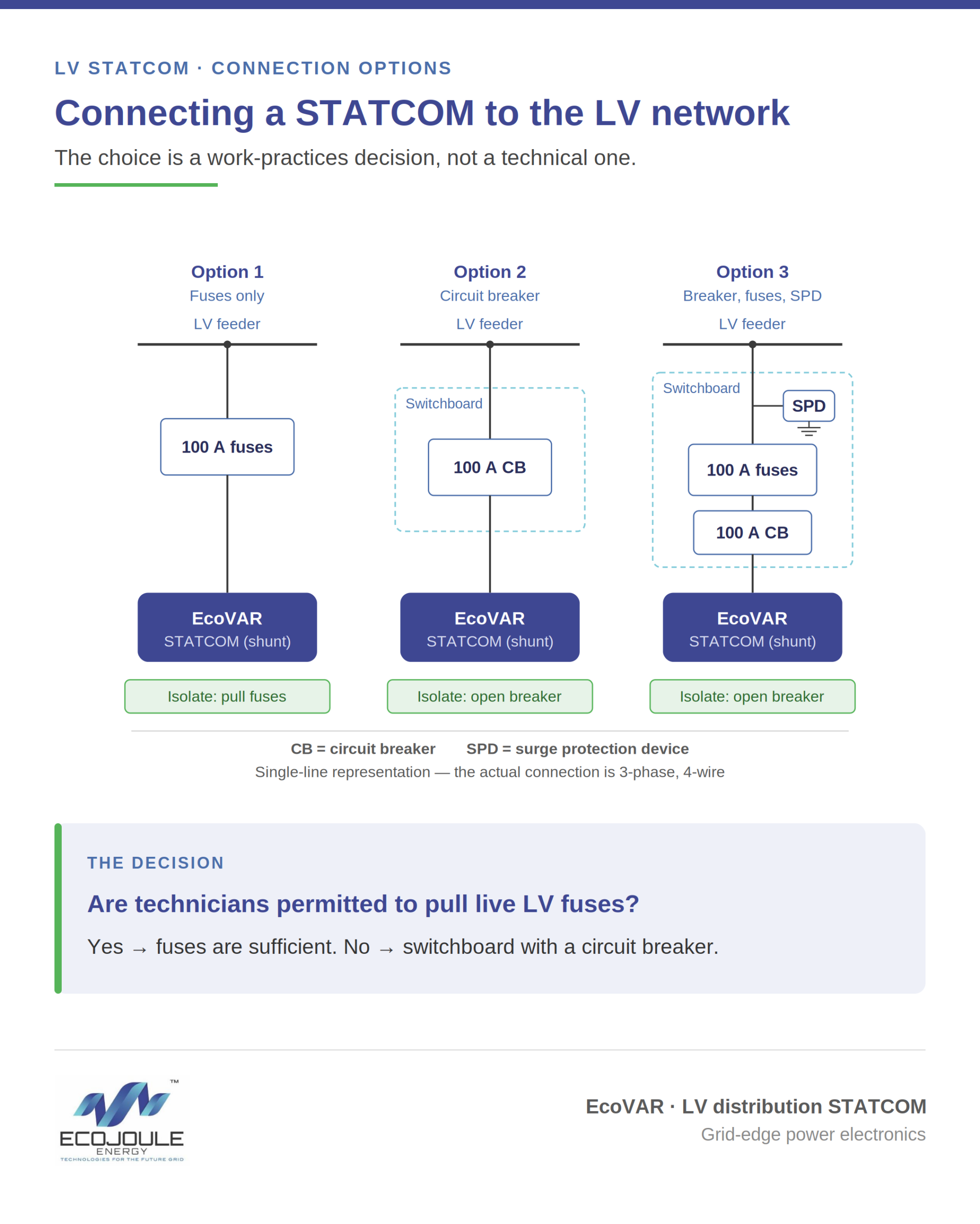
How a STATCOM connects to the LV network is a work-practices decision, not a technical one. The unit performs identically across every arrangement below — what changes is only how technicians isolate and power it down.

The shunt connection

A low voltage distribution STATCOM, such as the EcoVAR, connects to the LV feeder as a shunt device — it taps the network in parallel rather than in series. The feeder continues to carry its normal load; the STATCOM draws from the same connection to inject or absorb reactive current per phase. Because the connection is parallel, the feeder does not need to be de-energised to connect or remove the unit. Only the shunt tap point is worked, so there is no customer outage to bring a STATCOM into or out of service.

Every shunt connection needs a device between the STATCOM and the feeder that provides overcurrent protection and a means of isolation. Three arrangements are common. The choice is driven by the utility’s work practices and risk appetite — not by any difference in how the STATCOM performs. All three deliver identical operation.

Option 1 — Outdoor fuses

The lowest-cost method is a set of outdoor fuses, rated at 100 A, connecting the STATCOM to the overhead line on the shunt circuit.

The 100 A rating reflects the EcoVAR’s operating profile and its thermal environment. Full rated current is 63 A continuous, with a short-time capability of 1.5 × rated (about 95 A) under fault conditions. Most off-the-shelf MCBs derate their current rating at elevated ambient temperatures; at the EcoVAR’s 50 °C maximum, a marginally-sized breaker could trip spuriously at full output. Rating the device at 100 A holds margin above the derated threshold, so it carries full load without nuisance operation while remaining low enough to protect the connection. The rating is standardised at 100 A for both the fuse and circuit-breaker arrangements.

This is the fastest, simplest and most economical arrangement, with the fewest components in the circuit and therefore the fewest potential points of failure. Isolation is achieved by pulling the fuses. Because the STATCOM draws its operating supply from the same connection, removing the fuses is also the only way to override the unit and power it down.

The constraint is operational: some utilities’ work practices prohibit technicians from pulling live LV fuses. Where that rule applies, fuses alone are not a workable isolation method.

Option 2 — Switchboard with circuit breaker

For utilities that do not permit live fuse pulling, the connection is made through a small outdoor switchboard on the shunt circuit, between the STATCOM and the LV feeder. The switchboard houses a circuit breaker rated at 100 A.

The circuit breaker is a load-break device. It provides a rated switching point that brings the STATCOM in and out of service without pulling fuses, satisfying work practices that prohibit live fuse operation. The trade-off is one additional component and the associated cost, in exchange for an operator-friendly switching point.

Option 3 — Switchboard with circuit breaker, fuses and surge protection

The most conservative utilities add backup fuses and surge protection to the switchboard. The fuses provide backup overcurrent protection and fault coordination; the surge protection guards against transient overvoltages entering from the LV network.

This should be weighed carefully. Every additional device is a potential point of failure and a maintenance item. The marginal protection gained needs to be balanced against reduced overall reliability, a larger enclosure, and higher lifecycle cost.

Choosing an arrangement

The STATCOM operates the same way in all three cases. Match the connection arrangement to your work practices and your risk appetite, and avoid adding components whose protection you will not use. For most utilities the decision comes down to a single question: are technicians permitted to pull live LV fuses? If yes, fuses are sufficient. If no, a switchboard with a circuit breaker is the practical minimum.

Free Midday Power Comes With a Technical Catch

By Mike Wishart, Founder & CEO, EcoJoule Energy

As Australia accelerates its transition to renewable energy and retail energy prices continue to rise, initiatives like the Commonwealth Government’s Solar Sharer program are a positive step forward.

Encouraging households to use electricity during the middle of the day, when rooftop solar generation is at its peak, makes sense. It rewards consumers, supports clean energy utilisation, and helps reduce reliance on fossil fuel generation during other parts of the day.

However, as with any major shift in how and when energy is consumed, there are technical realities that must be carefully managed.

The Solar Sharer concept is simple: offer households a defined window of free or heavily discounted electricity during peak solar production hours. The goal is to soak up excess generation and avoid curtailment. But when thousands, or potentially millions, of households respond to the same pricing signal at the same time, the impact on local low-voltage networks can be significant.

Electricity distribution networks were not designed for synchronised behaviour at this scale. Historically, household demand has been relatively diverse and staggered. People cook, run appliances, and charge devices at different times. This natural diversity smooths out demand peaks.

Programs like Solar Sharer risk compressing that diversity into a narrow window. When the free power period begins, EV chargers ramp up simultaneously. Home batteries switch into charging mode. Pool pumps, air conditioners, hot water systems, and high-load appliances are programmed to start. While the intent is to align demand with solar supply, the local network can experience rapid voltage rises, swings, and phase imbalances.

Voltage management at the low-voltage level is becoming one of the most critical challenges of the energy transition. High rooftop solar penetration already creates periods of elevated voltage in many suburbs. Adding synchronised demand spikes on top of high generation can cause voltage instability in both directions.

These fluctuations are not just theoretical. Excessive voltage swings can trigger inverter protection settings, leading to solar export curtailment. Sensitive equipment can also be affected by poor power quality. Transformers and distribution assets may experience additional thermal stress. Over time, unmanaged localised stress accelerates wear and increases maintenance costs for network operators.

Importantly, this is not an argument against Solar Sharer or similar programs. On the contrary, they are well-intentioned and necessary as we rethink how to better integrate distributed renewable energy. But price signals alone are a blunt instrument. They need to be supported by intelligent, localised voltage and power quality management.

The grid is no longer a one-way system. It is dynamic, bidirectional, and increasingly decentralised. That means solutions must exist not only at substations and along feeders, but also behind the meter, within homes, businesses, and community assets.

Smart voltage regulation technology can provide the responsive buffering required to smooth these synchronised events. By dynamically absorbing or supplying reactive power, managing voltage levels in real time, and stabilising local phases, advanced systems can prevent the cascading effects of large-scale behavioural shifts.

This is where infrastructure innovation becomes critical. The energy transition is not just about adding more solar panels or batteries. It is about ensuring that the foundational electrical architecture can handle new usage patterns safely and reliably.

At EcoJoule Energy, we see this challenge firsthand. Our EcoVAR and EcoSTORE technologies are specifically designed to strengthen low-voltage networks in high renewable penetration environments. EcoVAR actively manages voltage and power factor in real time, smoothing fluctuations and improving power quality. EcoSTORE provides fast-response energy storage that can absorb excess generation or support demand spikes, reducing strain on local assets.
Together, these systems help create a more resilient and flexible grid at the edge. They allow innovative programs like Solar Sharer to succeed without compromising stability. Instead of networks reacting to volatility, they become adaptive and self-balancing.

Australia is leading the world in rooftop solar adoption. That leadership brings both opportunity and responsibility. As we introduce new market mechanisms to better utilise renewable energy, we must ensure the technical foundations keep pace.

The future of energy is distributed, digital, and dynamic. By combining smart policy with smarter infrastructure, we can unlock the full value of programs like Solar Sharer — delivering lower costs, cleaner power, and a stable grid for all Australians.

The transition is happening. The question is not whether we move forward, but how intelligently we do it.

About Mike Wishart

Electronics industry veteran Mike Wishart founded EcoJoule Energy in 2014 after a long career in the power electronics industry. EcoJoule Energy develops and deploys Low Voltage Distribution STATCOMs and Battery Energy Storage Systems (BESS) for electricity distribution networks. The company’s EcoVAR platform is in service across four continents. In 2025, the company raised $15 million of growth capital from investors, including Ellerston Capital and the Clean Energy Finance Corporation (CEFC).

EcoJoule Appoints NOJA Power’s Martin van der Linde as Chief Commercial Officer

EcoJoule Energy, a leading Australian energy technology company focused on improving grid stability and enabling renewable integration, has announced the appointment of former NOJA Power executive Martin van der Linde as Chief Commercial Officer (CCO).

As Chief Commercial Officer, Mr van der Linde will lead EcoJoule’s global commercial strategy, including market expansion, customer engagement and revenue growth.
Martin joins EcoJoule after more than 13 years in various roles with NOJA Power, most recently as General Manager Marketing. He is a seasoned management, marketing and engineering leader with extensive international experience.

An accomplished communicator, Martin has presented to executives, engineers, conferences and training audiences across 23 countries. He has been published in eight industry magazines on topics related to power systems, utilities and the broader energy sector.

Martin is a member of Engineers Australia and a member of the Electrical Energy Society of Australia (EESA).

EcoJoule Founder and CEO Dr Mike Wishart said Mr van der Linde was a widely-respected leader in the energy industry and he would play a crucial role in EcoJoule’s continued growth.

“Martin brings a rare combination of engineering depth and commercial acumen, which is exactly what EcoJoule needs as we scale,” Dr Wishart said.

“His ability to apply engineering principles to marketing and commercial strategy will be instrumental in accelerating our growth both in Australia and internationally.”

Mr van der Linde said he was excited to be joining EcoJoule at such an important time in their history.

“EcoJoule is at the forefront of solving one of the most critical challenges facing modern electricity networks,” Mr van der Linde said.

“I’m excited to help scale the company’s commercial operations and bring its innovative technologies to more markets globally.”

With a growing customer base that includes major network operators such as Endeavour Energy, Essential Energy, Ausgrid and AusNet Services, EcoJoule is playing a key role in enabling a more stable, resilient and renewable-ready electricity grid.

EcoJoule Energy’s technology platforms include pole-mounted community energy storage units that store the excess solar energy generated by residents for later use, and a voltage regulation device to help integrate more renewables into the grid.

EcoJoule Appoints Trevor Armstrong as Non-Executive Director

EcoJoule Energy, a leading Australian energy technology company focused on improving grid stability and enabling renewable integration, has announced the appointment of former senior Ausgrid executive Trevor Armstrong as a Non-Executive Director.

As Non-Executive Director, Mr Armstrong brings significant board-level experience and strategic oversight, and will support EcoJoule’s governance, growth strategy and engagement with key stakeholders across the energy sector.

EcoJoule Founder and CEO Dr Mike Wishart said the appointment would strengthen the company’s governance and strategic capability as it continued to scale its operations across Australia and international markets.

“Trevor brings valuable experience and insight that will support EcoJoule’s continued growth,” Dr Wishart said.

“As demand increases for technologies that help electricity networks manage the impacts of distributed energy resources like rooftop solar, strong leadership and governance are critical to delivering on our strategy.”

Trevor has more than 35 years’ of experience in the energy sector. He has held senior executive roles with Energy Australia, Networks NSW and Ausgrid, including interim Chief Executive Officer and Chief Operating Officer.  More recently, Trevor was the Chief Executive of ACEREZ, the Network Operator of the first renewable energy zone in NSW.

Trevor is currently on the Board of Power and Water in the Northern Territory and a Partnership Representative on ACEREZ. He has served on the Reliability Panel of the Australian Energy Market Commission, and Chair of CIGRE Australia.

EcoJoule is playing a key role in enabling a more stable, resilient and renewable-ready electricity grid. And works with a growing client base that includes major network operators such as UK Power Networks (UKPN), Endeavour Energy, Western Power, Essential Energy, Ausgrid and AusNet Services,

EcoJoule Energy’s technology platforms include pole-mounted community energy storage units that store the excess solar energy generated by residents for later use, and a voltage regulation device that helps integrate more renewables into the grid.