The LV D-STATCOM as a Permanent Network Asset

Phase balancing and harmonic mitigation before, during and after augmentation

Summary

Low voltage augmentation adds capacity and lowers impedance. It does not redistribute load between phases, and it does not remove harmonic current from the network. Both problems are growing on distribution networks for the same reason augmentation is being triggered in the first place: single-phase rooftop PV, single-phase EV charging, and inverter-connected load.

An LV D-STATCOM should therefore be specified as a permanent network asset. It performs two functions, continuous phase balancing and active harmonic filtering. No passive augmentation performs this at any cost, and the drivers behind both intensify as a feeder’s load and inverter population grow. Deployed early, it releases capacity from conductors and transformers that are already in the ground. After augmentation eventually proceeds for thermal reasons, it continues to manage the conditions the augmentation was never able to address.

This release sets out the engineering behind that position.

1.  Augmentation changes impedance, not composition

Conventional LV remediation works through impedance. Reconductoring increases conductor cross-section. A larger distribution transformer presents a lower source impedance. Splitting a feeder or adding a substation shortens the electrical distance to the worst-served customer. In each case the voltage consequence of a given current is reduced.

Phase imbalance is not a function of impedance. It is a function of how load and generation are distributed across the three phases, and of how that distribution varies through the day. Connection schedules are balanced at design. Real-time loading is not. Diversity between customers, uneven single-phase PV, and the arrival of 7 kW single-phase EV chargers all produce unequal phase currents on a nominally balanced feeder.

Augmentation attenuates the symptom. The neutral current that flows because of unequal phase loading is unchanged by a larger conductor; the voltage difference it produces between phases is reduced, in proportion to the impedance reduction achieved. Where the imbalance is severe, that reduction may not be sufficient. Where load subsequently grows — and augmentation is generally triggered by load growth — the voltage consequence returns.

An LV D-STATCOM addresses the current, not the voltage drop it produces. The EcoVAR transfers real power between phases through its DC link, drawing from the lightly loaded phases and supplying the heavily loaded one. The phase currents seen upstream of the point of connection are equalised. This is a continuous, closed-loop function that follows the load pattern through the day. No passive asset can do this.

2.  Hosting capacity is set by the worst phase, not the average

Where single-phase PV is unevenly distributed, the normal case, since installation follows customer decisions rather than network planning, the constraining phase reaches the upper statutory voltage limit while the other two retain headroom. Under AS 4777.2, inverters on the constrained phase respond with volt-watt curtailment. Export is lost on one phase while capacity sits unused on the others.

Augmentation raises hosting capacity uniformly across all three phases. It does not correct the asymmetry, so the worst phase remains the binding constraint. The headroom already present on the other phases stays inaccessible.

Phase balancing recovers that headroom. By equalising the phase currents, the voltage rise is shared rather than concentrated, and the curtailment threshold on the worst phase is pushed back. The gain is available from the existing conductor, at the existing rating, without an outage.

This is the more significant point for a network with a mature rooftop PV population: the constraint is frequently distributional rather than absolute. Solving it distributionally releases capacity the utility has already paid for, and returns the benefit to every customer on the feeder rather than to those who happen to sit on the favourable phase.

3.  Harmonic current is not removed by a larger conductor

Harmonic current injection on LV feeders is increasing from PV inverters, EV chargers, variable speed drives, switched-mode power supplies and LED lighting. The resulting voltage distortion is the product of the injected harmonic current and the network’s harmonic impedance at each order.

Lowering the source impedance through augmentation does reduce harmonic voltage distortion at the point of measurement, for a given injected current. That is a real benefit and worth stating plainly. It does not resolve the problem, for three reasons.

The current still flows.  A lower impedance path means harmonic current propagates further upstream, through the distribution transformer and toward the MV network, rather than being attenuated locally. The distortion is relocated rather than removed.

Transformers still carry it.  A replacement transformer carries the same harmonic load current and is subject to the same additional eddy current and stray losses. Thermal derating for harmonic content applies to the new asset as it did to the old one.

An active harmonic filter operates on the current directly. The EcoVAR measures the harmonic content at the point of connection and injects compensating current in counter-phase, so the distorted current is cancelled locally and does not propagate upstream. This function is independent of network impedance, and therefore unaffected by whether augmentation has been carried out. Its 864 V DC link provides the voltage headroom needed to slew injection current fast enough to track higher-order components, and to retain full capability at the top of the statutory voltage range.

4.  Deployment: same day, no outage, utility-controlled

The operational profile is as important to the case as the electrical performance, because it is where the contrast with augmentation is widest.

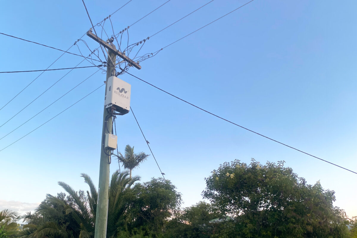
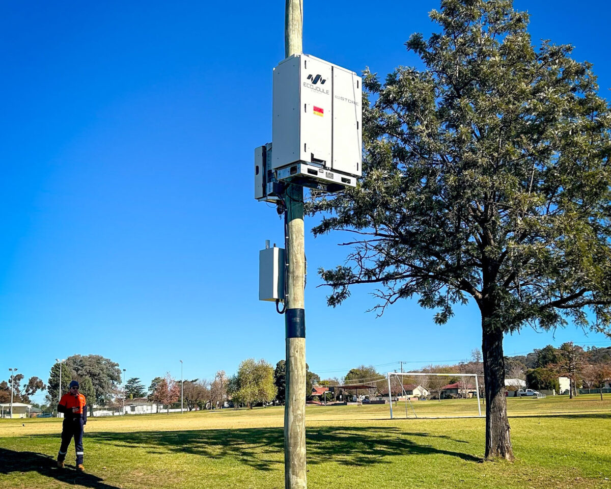
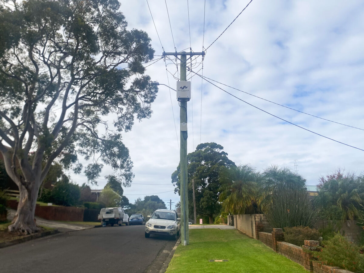
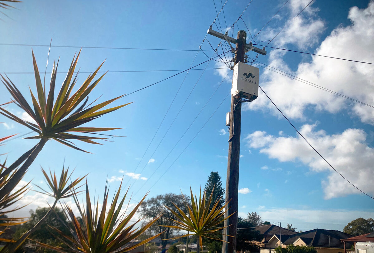
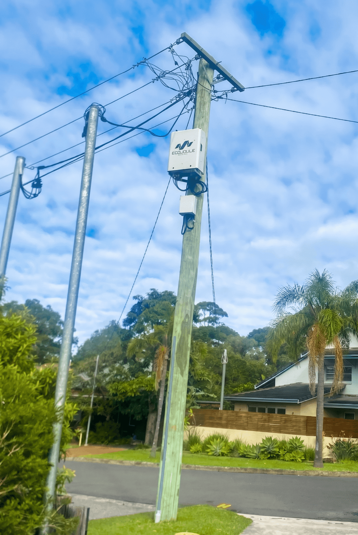
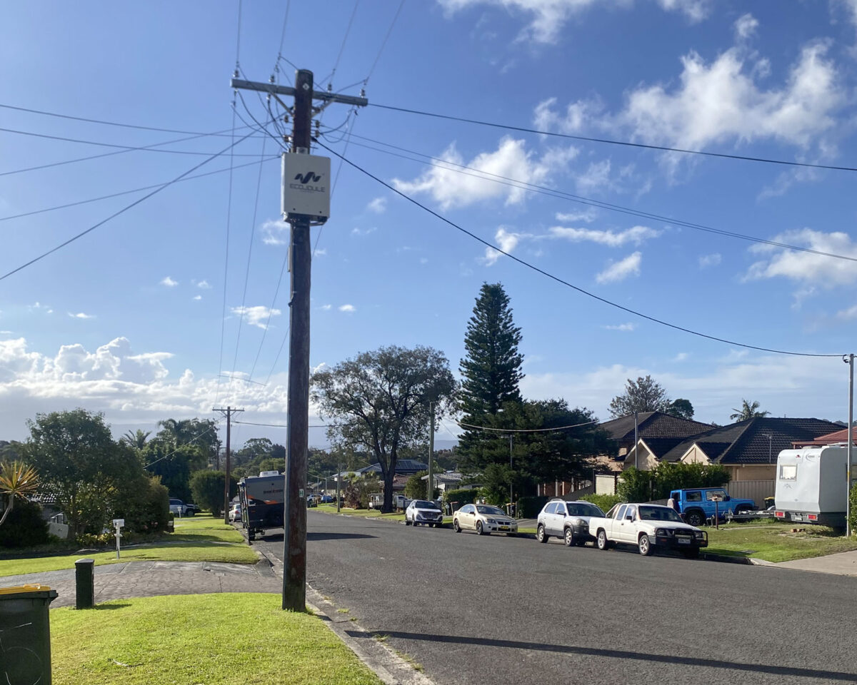
The EcoVAR is pole-mounted and connects in parallel through a set of LV fuses. Installation is carried out live. No customer outage is required, no switching programme, no civil work, no customer notification cycle. A crew installs and commissions in a single visit, on the same day the unit arrives on site.

Once energised, the unit is the utility’s asset in every operational sense. It logs phase voltages, currents, neutral current and harmonic content continuously. Settings are adjusted and firmware updated remotely, by the utility, without a site visit. There is no dependency on the manufacturer for routine operation, and no scheduled maintenance to programme.

Set against an augmentation that requires design, approval, procurement, outage planning and construction — and a capital cost one to two orders of magnitude higher — the D-STATCOM is a decision that can be made and executed inside the time it takes to scope the alternative.

5.  Sequencing across the feeder’s life

The functions above suggest an order of works rather than a choice between alternatives.

Deploy on the existing network.  Where a feeder shows voltage excursions with a significant imbalance component, an EcoVAR increases the usable capacity of the conductors and transformer already installed. Endeavour Energy and Ausgrid crews are completing installations in under two hours. Voltage complaints and PV curtailment are addressed on a timescale of weeks.

Augment when the constraint is genuinely thermal.  Load growth eventually consumes the headroom that balancing releases. When the limit is the current-carrying capacity of the conductor or the rating of the transformer, augmentation is the correct answer and a D-STATCOM is not a substitute for it.

The D-STATCOM continues.  At this point the feeder carries more load, more PV and more inverter-connected equipment than when the unit was installed. The imbalance and harmonic drivers are stronger, not weaker. The EcoVAR continues to perform phase balancing and active harmonic filtering — the two functions the augmentation did not deliver — on a network that now needs them more. It also continues to log at that point, which for most utilities represents a rare permanent measurement location in the LV network.

The unit’s role broadens over the life of the feeder: constraint relief first, then power quality management and network visibility. It is specified once and it stays.

6.  Understanding Siting of the EcoVAR

Siting is not among the constraints, and a few spans either side of the worst-served customer makes little practical difference. The unit does not warrant a detailed siting study. Given the STATCOM exploits upstream impedance, most installations range between halfway and ¾ of the way down an LV feeder. On a cost effective asset such as the EcoVAR, displacing works that cost orders of magnitude more, engineering effort spent optimising position is effort spent for no return. More detail on site selection is covered here: Site Selection for the EcoVAR D-STATCOM: Optimising Placement 

7.  Identifying a candidate feeder

The indicators are measurable and most utilities already hold the data. This is a screening exercise of minutes, not a study:

  1. Voltage excursions on the feeder. If it’s 3 phase excursions, the STATCOMs reactive compensation manages it. Imbalance is managed by the combination of Reactive and Active Power Transfer
  2. Uneven single-phase PV and EV Charger distribution across phases
  3. Rising voltage total harmonic distortion, or customer equipment complaints without a corresponding thermal constraint

Where any of these indicators are present, a single unit on a live feeder produces measured before-and-after evidence from the utility’s own network within weeks — at a fraction of the augmentation cost, and with no outage required to obtain it.

EcoJoule Energy designs and manufactures the EcoVAR LV D-STATCOM in Brisbane, Australia.

EcoJoule Energy Secures GET Grant to Improve Grid Efficiency

Australian energy technology company EcoJoule Energy has secured a Grid Enhancing Technologies Grant (GET) Program to support the deployment of its innovative technology that improves the efficiency and capacity of Australia’s electricity networks.

EcoJoule Energy is one of 14 successful grant recipients announced by Minister for Climate Change and Energy Chris Bowen as part of a $30 million investment in projects designed to create a smarter, more efficient and resilient electricity system.

The funding will support EcoJoule Energy to demonstrate how advanced network optimisation technologies, including the EcoVAR Alto and the EcoSTORE Alto, can help electricity distribution networks manage voltage, increase their capacity to accommodate renewable energy and make better use of existing infrastructure.

EcoJoule Energy CEO Dr Mike Wishart welcomed the grant and thanked the Australian Government for supporting the continued development and deployment of Australian-developed and Australian-made grid technology.

“We welcome the Australian Government’s investment in Grid Enhancing Technologies and thank Minister Bowen and the Department of Climate Change, Energy, the Environment and Water for their support,” Dr Wishart said.

“Australia’s energy system is undergoing a fundamental transformation as rooftop solar, batteries, electric vehicles and other distributed energy resources become a larger part of the energy mix,” Dr Wishart said.

“This transition is creating new challenges for electricity networks, particularly at the low-voltage level. It is also creating an opportunity to use smart, flexible technologies to get more from the infrastructure we already have.

EcoJoule Energy develops and manufactures advanced power quality and battery energy storage systems for distribution electricity networks in Australia and international markets. The company’s technology is currently in use in nearly a dozen countries on four continents.

The technology helps network operators manage voltage, improve power quality and accommodate growing levels of customer energy resources (CER).

Dr Wishart said the GET Grant Program recognised the important role Australian innovation would play in modernising the nation’s electricity grid.

“Australia is a global leader in the adoption of rooftop solar, but realising its full value will require greater investment in the distribution networks that connect homes and businesses,” he said.

“Network optimisation technologies can address voltage constraints and release additional capacity without relying solely on major new infrastructure.

“This project will provide valuable evidence about how these technologies can be deployed more broadly to benefit networks, consumers and the wider energy system.

“EcoJoule is proud to be contributing Australian-developed technology and expertise to this important national program.”

The GET Grant Program forms part of the Australian Government’s Rewiring the Nation program. The 14 successful projects will operate across Queensland, New South Wales, Victoria, Western Australia, South Australia and the Australian Capital Territory.

Specifying distributed storage for an unbalanced grid: Four things that matter

Four criteria that determine whether distributed storage holds up in a low-voltage network that is no longer balanced.

The low-voltage network is no longer balanced, and it is not returning to a balanced state. Single-phase rooftop solar, single-phase EV charging and uneven load growth mean that voltage imbalance across the three phases is now the normal operating condition on most feeders.

This has a consequence for distributed storage that is often overlooked in procurement. The reliability of a distributed battery is not only a question of cell chemistry or warranty terms. It is a question of whether the asset keeps delivering in the network as it actually is, whether it avoids the failure modes that take enclosed batteries offline, whether it can be restored quickly when it needs service, and whether the operator retains control of it once it is connected.

Those four criteria are where a specification for distributed storage should focus.

Correcting the network the asset operates in

Modern networks are being driven towards unbalance. The prevalence of high power single phase generation and loads – such as PV or EV charging – introduce unbalance that interferes with 3 phase inverters that lack STATCOM capabilities.

In an unbalanced feeder, the modern utility grade BESS with STATCOM capabilities regulate each phase independently, absorbing or injecting reactive current per phase to bring phase voltages back within limits, and it maintains that correction continuously while it charges or discharges real power. It creates its own voltage headroom, then uses it.

A conventional three-phase BESS injects balanced current across all three phases. Where the feeder is already unbalanced, or sitting near a per-phase voltage limit, that inverter has little room to deliver its rated real power. It curtails, or it trips. The more single-phase DER and EV charging on the feeder, the more often this occurs.

As imbalance becomes the standard condition, an asset that corrects the condition it operates in is materially more resilient than one that depends on the condition being favourable. The specification point is independent per-phase real and reactive control, maintained continuously during charge and discharge.

Operating without air conditioning

This removes one of the most common failure and maintenance points in enclosed battery systems. Air-conditioning is an active mechanical system with its own compressors, fans and refrigerant circuit. When it fails, the battery it protects is exposed, and it is a recurring service item over the life of the asset.

It also removes the parasitic load that air-conditioning draws continuously, which improves round-trip efficiency: less of the stored energy is lost to running the enclosure. It lowers the acoustic footprint of the asset, verified by type testing, which matters wherever storage is sited near residential or community areas.

The specification points are an auxiliary-load ceiling, an acoustic limit expressed in dB(A) at a stated distance, and no active mechanical cooling as a single point of failure. Passive cooling meets these on engineering merit.

Modular service by unit swap

Modern distributed storage keeps the inverter/STATCOM and the battery enclosure as separate modules. Damage or a scheduled service event in one module is contained to that unit; the other is unaffected.

For the operator, this changes the maintenance model. Field service becomes a module swap against a spare, rather than an on-site repair. The site is returned to service in a short, planned window, and the damaged module is repaired off-site. Spares can be pooled across a fleet, so the effective mean time to restore is the time to swap a unit rather than the time to diagnose and rebuild one in the field.

Uptime therefore becomes a property of the deployment model, not only of the hardware. The specification point is independent replaceability of the power conversion and storage modules without decommissioning the other.

Operator control of the asset

Cybersecurity compliance is paramount, and legacy BESS that require a manufacturer connection or phone home introduce cybersecurity risks. Modern BESS communicate over, widely supported protocols: DNP3 and Modbus, fully controlled by the operating utility. There should be no mandatory link back to the manufacturer, and the asset does not require any connection to the vendor to operate.

This means the network operator owns the control, software and firmware lifecycle. The asset is held to the operator’s own compliance and security posture, and kept within network compliance conditions by the operator. Remote support from EcoJoule is available if the operator wants it, but it is optional, not built into how the system runs.

There are power conversion systems manufactured in Australia. For operators applying trusted-origin or sovereign-supply criteria to grid-connected devices, an increasingly common part of procurement, that origin is a material point.

The specification points are open protocol support, no mandatory vendor communications, operator ownership of the firmware lifecycle, and trusted origin of the power conversion equipment.

What this means for planners

A reliable distributed battery is one that keeps delivering in an unbalanced network, avoids the failure modes that take enclosed batteries offline, can be restored inside a short planned window, and stays under the operator’s control. None of these is decided after installation. They are architectural choices — a per-phase STATCOM front end, passive cooling with no active HVAC to fail, separable modules, and open protocols with no vendor dependency — made in the design of the asset.

These key design choices are integrated in the EcoJoule EcoSTORE pole mount BESS.

Specified as outcomes rather than mechanisms, these four criteria give a procurement team a defensible basis for selecting distributed storage that will hold up in the network as it actually operates.

EcoJoule Teams Up With Hitachi Energy And Eve Energy For Next Generation Utility-Scale BESS Platform

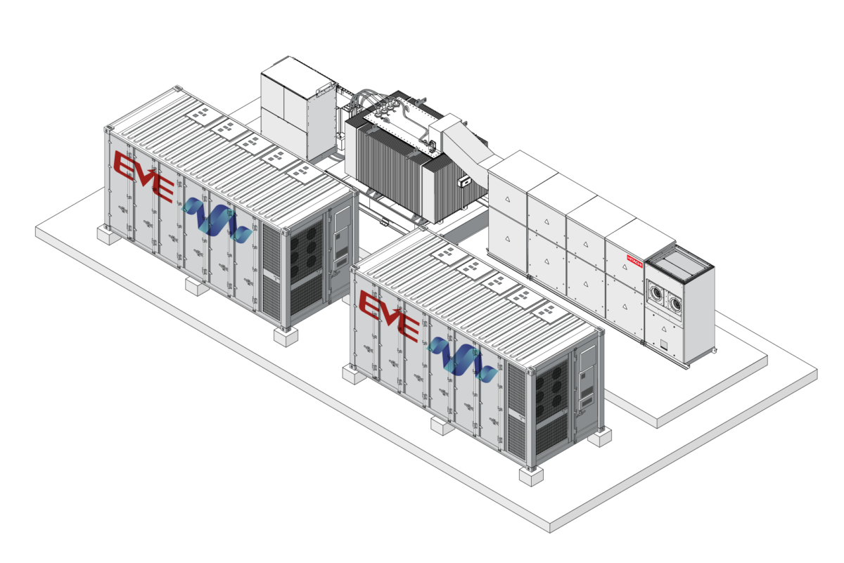
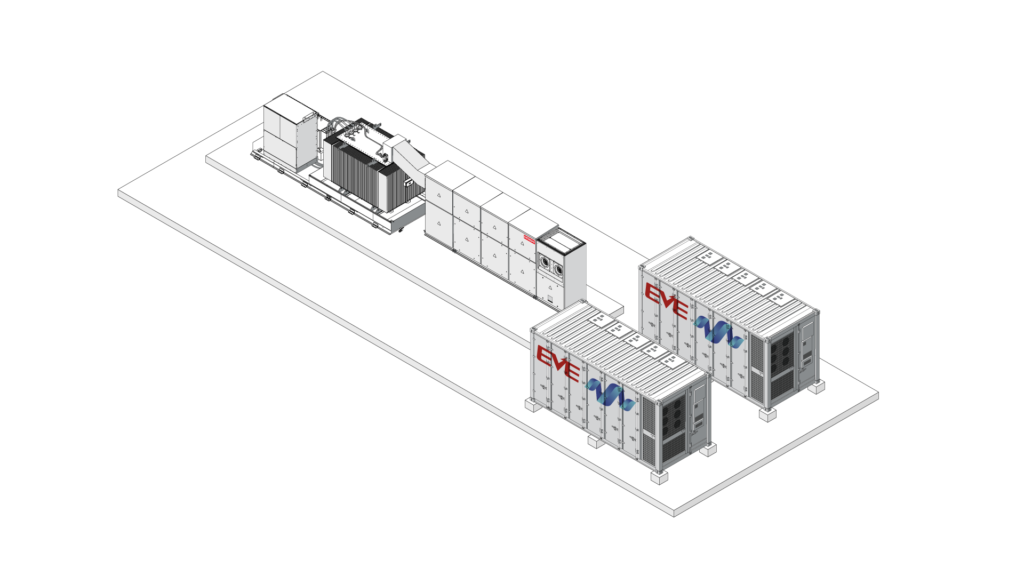
EcoJoule Energy has teamed up with Hitachi Energy, a global leader in electrification, and battery manufacturer EVE Energy to launch a new industry-leading sub-5 MW battery energy storage system (BESS) that will help alleviate network constraints and maximise existing and new consumer energy resources (CER).

EcoSTORE MEGA is engineered for both grid-following and grid-forming applications and integrates EVE Energy’s 5 MWh MR Giant LFP battery containers with Hitachi Energy’s WD4 power conversion system and centralised power plant controller. This architecture enables precise active and reactive power control for utility-scale projects.

The system is built around a standard 4.98 MW/5 MWh block architecture that can support a range of energy durations using a common PCS platform. This modular approach allows developers and utilities to scale capacity over time while maintaining consistent performance across sites.

The modular system has been designed and integrated in Australia to meet the operational, regulatory and environmental requirements of local electricity networks. The system combines Hitachi Energy’s bi-directional power conversion systems and control technology with high-efficiency lithium iron phosphate battery containers from EVE Energy.

The EcoSTORE MEGA will allow network operators to alleviate network constraints on high-voltage feeders and substations, enable more CER connections,  and reduce reliance on large-scale generation solutions, which are facing high costs and social challenges.

EcoJoule Energy Founder and CEO Dr Mike Wishart said the partnerships reflected the importance of combining globally proven technology with strong local engineering and integration capability.

“Battery storage is rapidly becoming critical infrastructure for the Australian energy system, and we believe there is a real opportunity to grow in the space between small household batteries and large utility-scale batteries,” he said.

“EcoSTORE MEGA reflects that philosophy and combines proven Tier-1 components with EcoJoule’s deep experience in power electronics, system integration and grid compliance to deliver a reliable and scalable energy storage platform designed specifically for Australian network conditions.”

EcoJoule Chief Commercial Officer Martin van der Linde said EcoJoule Energy’s role as a local integrator was critical to ensuring global battery technology performs effectively within Australia’s complex grid environment.

“Successful battery projects require more than high-quality hardware. They require a deep understanding of local grid behaviour, compliance requirements and network expectations,” Mr van der Linde said.

“As an Australian engineering and integration partner, EcoJoule works closely with developers, utilities and network operators to ensure systems are designed, commissioned and operated to perform in real-world conditions,” he said.

“By integrating global technology locally, we can customise each system for Australian standards and operating environments while providing onshore engineering, commissioning and long-term support.

“With EcoJoule managing the entire engineering and rollout, we can get systems on the ground quickly and efficiently reducing delivery risk for our customers and helping ensure these assets perform reliably over their entire operational life.”

EcoJoule’s other products include:

  • EcoVAR ALTO is a pole-mounted low voltage STATCOM that regulates voltage levels on distribution networks in real time. The technology enables network operators to integrate more consumer energy resources and electrification technologies without costly grid upgrades.
  • EcoSTORE ALTO is an intelligent, Australian-made, pole-mounted BESS/STATCOM  that improves energy quality, reliability, and efficiency, particularly in fringe-of-grid and renewable-heavy networks.

EcoSTORE MEGA has been designed to meet Australian and international safety and grid compliance standards, including AS/NZS and IEC requirements. The system delivers high efficiency, fast control response and long-term operational reliability in demanding utility environments.

The highly integrated and standardised design simplifies transport, installation, connection and commissioning, while comprehensive deployment and operator training programs support project delivery.

Established nearly a decade ago, EcoJoule Energy is a 100% Australian-owned company providing innovative solutions to help electricity distributors integrate renewable energy and manage grid reliability.

In early 2025, the company secured a $15 million capital investment from Ellerston Capital and the Clean Energy Finance Corporation (CEFC) to support the company’s national and international growth ambitions.

For more information and specifications, visit the EcoSTORE MEGA page.

Media enquiries to:
Ben Ready
+61 415 743 838
ben@rgcmm.com.au.

Responding to load-switching voltage sags on weak LV networks

The problem

When a large load switches onto a low-voltage feeder (a fast EV charger, a heat-pump compressor, a welding set, an irrigation pump), it draws a step change in current. That current flows through the upstream impedance of the supply: the distribution transformer, the LV main, and the service conductor. On a weak network (high source impedance, low fault level) the resulting voltage drop is large enough to be seen as a sag at the point of connection and at neighbouring premises.

The drop is approximated by:

Two features of LV networks make this acute. First, the inrush of motors and switched-mode loads is reactive-heavy, so Q is momentarily large. Second, most large LV loads are single-phase, so the sag, and the voltage unbalance that comes with it, appears on one phase while the others are largely unaffected.

Conventional responses are poorly matched to the problem. Switched capacitor banks produce reactive output that falls with the square of voltage, giving least support exactly when voltage is depressed, and they cannot act per phase or respond within a cycle. On-load tap changers are too slow for switching events and act on the whole feeder rather than the affected phase. Reconductoring removes the constraint but requires capital and an outage.

How the EcoVAR responds

The EcoVAR is a shunt-connected LV distribution STATCOM. It measures voltage continuously and injects a controlled current at the point of connection to oppose the disturbance. Three characteristics matter for switching sags.

Current-source behaviour

As a voltage-source converter under closed-loop control, the EcoVAR’s injected current is set by its controller, not by the line voltage. Unlike a capacitor, its support does not collapse as voltage falls; it holds its commanded output through the sag, up to its rating.

Per-phase injection

The EcoVAR controls each phase independently. When a single-phase load causes an unbalanced sag, it supports the affected phase and corrects the unbalance without disturbing the other two — something a positive-sequence or three-phase-balanced compensator cannot do.

Fast closed-loop response

Power-electronic switching lets the converter react within a few cycles, fast enough to arrest the step a switching load produces rather than ride it out.

Because the same converter also performs active harmonic filtering, a load that both depresses voltage and injects harmonics (a drive or a charger) is addressed by one device.

What to expect, and how it scales

Reactive shunt compensation acts on voltage through the network reactance, X. The EcoVAR is strongest where the sag is reactive-dominated (motor inrush, switching transients) or unbalanced — which covers most LV switching events, and where per-phase injection corrects the sag and the unbalance together.

Where a sag is instead driven by a sustained, largely balanced real-power draw on a resistive feeder, reactive injection alone has less to work with. The EcoVAR can then be upgraded with EcoSTORE storage to supply the real-power component alongside its reactive support, addressing the P·R term of the voltage drop directly while retaining per-phase voltage control, phase balancing and harmonic filtering. The connection point and platform are unchanged; the same asset scales from reactive support to combined real-and-reactive support as the network’s needs grow.

In deployment

The EcoVAR installs without a network outage and retrofits to existing pole-mount (Alto) or ground-mount (Terra) sites. From a single shunt connection it provides per-phase voltage support, phase balancing and active harmonic filtering — relieving a switching-sag constraint without reconductoring or a transformer change.

Connecting a Low Voltage STATCOM to the Distribution Network

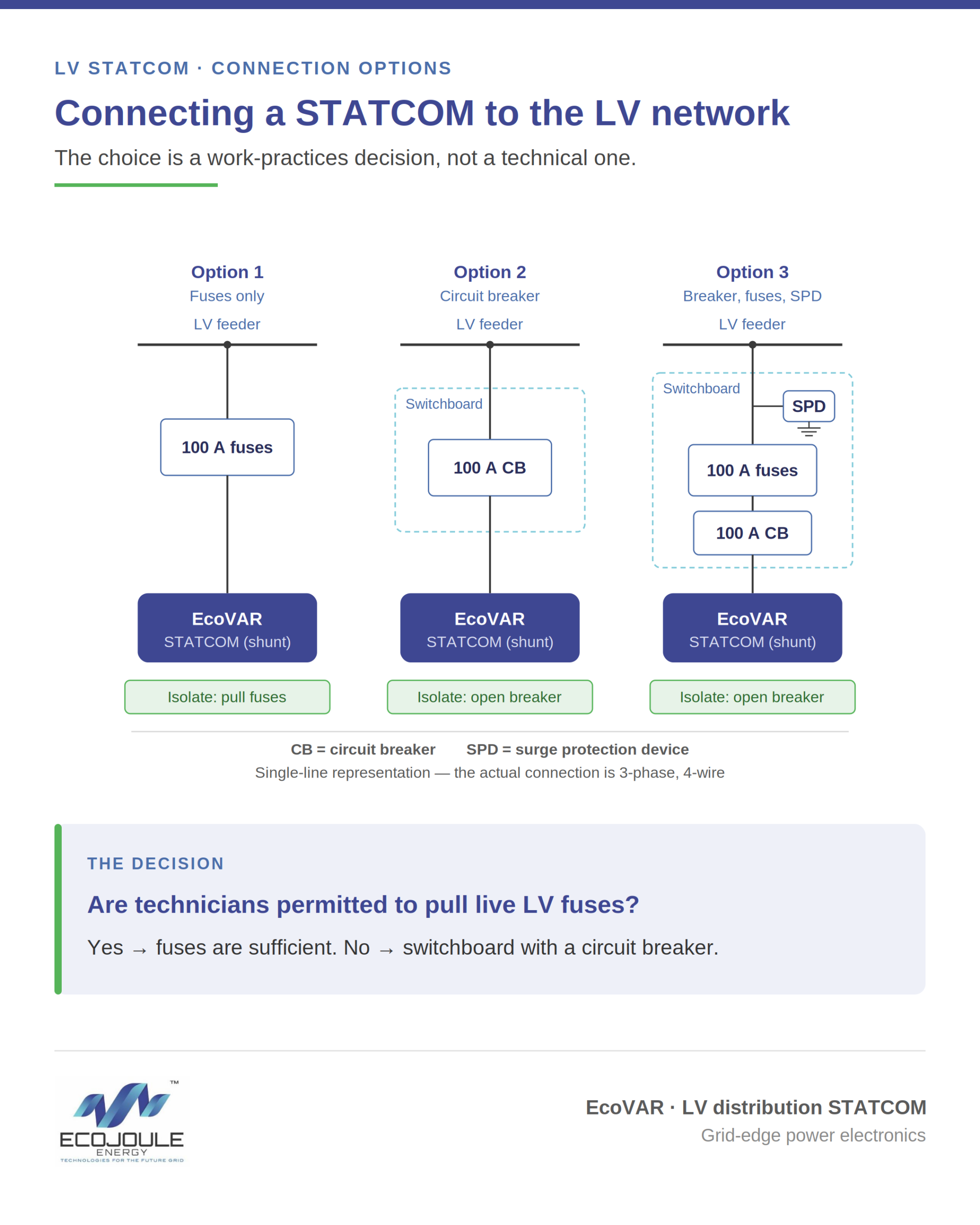
How a STATCOM connects to the LV network is a work-practices decision, not a technical one. The unit performs identically across every arrangement below — what changes is only how technicians isolate and power it down.

The shunt connection

A low voltage distribution STATCOM, such as the EcoVAR, connects to the LV feeder as a shunt device — it taps the network in parallel rather than in series. The feeder continues to carry its normal load; the STATCOM draws from the same connection to inject or absorb reactive current per phase. Because the connection is parallel, the feeder does not need to be de-energised to connect or remove the unit. Only the shunt tap point is worked, so there is no customer outage to bring a STATCOM into or out of service.

Every shunt connection needs a device between the STATCOM and the feeder that provides overcurrent protection and a means of isolation. Three arrangements are common. The choice is driven by the utility’s work practices and risk appetite — not by any difference in how the STATCOM performs. All three deliver identical operation.

Option 1 — Outdoor fuses

The lowest-cost method is a set of outdoor fuses, rated at 100 A, connecting the STATCOM to the overhead line on the shunt circuit.

The 100 A rating reflects the EcoVAR’s operating profile and its thermal environment. Full rated current is 63 A continuous, with a short-time capability of 1.5 × rated (about 95 A) under fault conditions. Most off-the-shelf MCBs derate their current rating at elevated ambient temperatures; at the EcoVAR’s 50 °C maximum, a marginally-sized breaker could trip spuriously at full output. Rating the device at 100 A holds margin above the derated threshold, so it carries full load without nuisance operation while remaining low enough to protect the connection. The rating is standardised at 100 A for both the fuse and circuit-breaker arrangements.

This is the fastest, simplest and most economical arrangement, with the fewest components in the circuit and therefore the fewest potential points of failure. Isolation is achieved by pulling the fuses. Because the STATCOM draws its operating supply from the same connection, removing the fuses is also the only way to override the unit and power it down.

The constraint is operational: some utilities’ work practices prohibit technicians from pulling live LV fuses. Where that rule applies, fuses alone are not a workable isolation method.

Option 2 — Switchboard with circuit breaker

For utilities that do not permit live fuse pulling, the connection is made through a small outdoor switchboard on the shunt circuit, between the STATCOM and the LV feeder. The switchboard houses a circuit breaker rated at 100 A.

The circuit breaker is a load-break device. It provides a rated switching point that brings the STATCOM in and out of service without pulling fuses, satisfying work practices that prohibit live fuse operation. The trade-off is one additional component and the associated cost, in exchange for an operator-friendly switching point.

Option 3 — Switchboard with circuit breaker, fuses and surge protection

The most conservative utilities add backup fuses and surge protection to the switchboard. The fuses provide backup overcurrent protection and fault coordination; the surge protection guards against transient overvoltages entering from the LV network.

This should be weighed carefully. Every additional device is a potential point of failure and a maintenance item. The marginal protection gained needs to be balanced against reduced overall reliability, a larger enclosure, and higher lifecycle cost.

Choosing an arrangement

The STATCOM operates the same way in all three cases. Match the connection arrangement to your work practices and your risk appetite, and avoid adding components whose protection you will not use. For most utilities the decision comes down to a single question: are technicians permitted to pull live LV fuses? If yes, fuses are sufficient. If no, a switchboard with a circuit breaker is the practical minimum.

Free Midday Power Comes With a Technical Catch

By Mike Wishart, Founder & CEO, EcoJoule Energy

As Australia accelerates its transition to renewable energy and retail energy prices continue to rise, initiatives like the Commonwealth Government’s Solar Sharer program are a positive step forward.

Encouraging households to use electricity during the middle of the day, when rooftop solar generation is at its peak, makes sense. It rewards consumers, supports clean energy utilisation, and helps reduce reliance on fossil fuel generation during other parts of the day.

However, as with any major shift in how and when energy is consumed, there are technical realities that must be carefully managed.

The Solar Sharer concept is simple: offer households a defined window of free or heavily discounted electricity during peak solar production hours. The goal is to soak up excess generation and avoid curtailment. But when thousands, or potentially millions, of households respond to the same pricing signal at the same time, the impact on local low-voltage networks can be significant.

Electricity distribution networks were not designed for synchronised behaviour at this scale. Historically, household demand has been relatively diverse and staggered. People cook, run appliances, and charge devices at different times. This natural diversity smooths out demand peaks.

Programs like Solar Sharer risk compressing that diversity into a narrow window. When the free power period begins, EV chargers ramp up simultaneously. Home batteries switch into charging mode. Pool pumps, air conditioners, hot water systems, and high-load appliances are programmed to start. While the intent is to align demand with solar supply, the local network can experience rapid voltage rises, swings, and phase imbalances.

Voltage management at the low-voltage level is becoming one of the most critical challenges of the energy transition. High rooftop solar penetration already creates periods of elevated voltage in many suburbs. Adding synchronised demand spikes on top of high generation can cause voltage instability in both directions.

These fluctuations are not just theoretical. Excessive voltage swings can trigger inverter protection settings, leading to solar export curtailment. Sensitive equipment can also be affected by poor power quality. Transformers and distribution assets may experience additional thermal stress. Over time, unmanaged localised stress accelerates wear and increases maintenance costs for network operators.

Importantly, this is not an argument against Solar Sharer or similar programs. On the contrary, they are well-intentioned and necessary as we rethink how to better integrate distributed renewable energy. But price signals alone are a blunt instrument. They need to be supported by intelligent, localised voltage and power quality management.

The grid is no longer a one-way system. It is dynamic, bidirectional, and increasingly decentralised. That means solutions must exist not only at substations and along feeders, but also behind the meter, within homes, businesses, and community assets.

Smart voltage regulation technology can provide the responsive buffering required to smooth these synchronised events. By dynamically absorbing or supplying reactive power, managing voltage levels in real time, and stabilising local phases, advanced systems can prevent the cascading effects of large-scale behavioural shifts.

This is where infrastructure innovation becomes critical. The energy transition is not just about adding more solar panels or batteries. It is about ensuring that the foundational electrical architecture can handle new usage patterns safely and reliably.

At EcoJoule Energy, we see this challenge firsthand. Our EcoVAR and EcoSTORE technologies are specifically designed to strengthen low-voltage networks in high renewable penetration environments. EcoVAR actively manages voltage and power factor in real time, smoothing fluctuations and improving power quality. EcoSTORE provides fast-response energy storage that can absorb excess generation or support demand spikes, reducing strain on local assets.
Together, these systems help create a more resilient and flexible grid at the edge. They allow innovative programs like Solar Sharer to succeed without compromising stability. Instead of networks reacting to volatility, they become adaptive and self-balancing.

Australia is leading the world in rooftop solar adoption. That leadership brings both opportunity and responsibility. As we introduce new market mechanisms to better utilise renewable energy, we must ensure the technical foundations keep pace.

The future of energy is distributed, digital, and dynamic. By combining smart policy with smarter infrastructure, we can unlock the full value of programs like Solar Sharer — delivering lower costs, cleaner power, and a stable grid for all Australians.

The transition is happening. The question is not whether we move forward, but how intelligently we do it.

About Mike Wishart

Electronics industry veteran Mike Wishart founded EcoJoule Energy in 2014 after a long career in the power electronics industry. EcoJoule Energy develops and deploys Low Voltage Distribution STATCOMs and Battery Energy Storage Systems (BESS) for electricity distribution networks. The company’s EcoVAR platform is in service across four continents. In 2025, the company raised $15 million of growth capital from investors, including Ellerston Capital and the Clean Energy Finance Corporation (CEFC).

The Per-Phase Compliance Trap

Low-voltage planning has long been able to treat a feeder as a balanced three-phase circuit. For most of the network’s history that was a safe assumption. High penetrations of single-phase distributed generation and single-phase load are ending it, and they do so in a way an aggregate check doesn’t catch.

Voltage compliance is assessed per phase. In Australia, the nominal is 230 V with a range of +10% / −6% (AS60038 and AS61000.300.1), and each phase at the point of supply has to sit inside that range, not the average of the three, each one independently.

Single-phase connections are where this bites. A rooftop inverter or an EV charger connects to one phase, not three. At low penetration the connections diversify across phases and across the day, and the feeder behaves close to balanced. At high penetration that diversity fails. PV exports on the phases it happens to sit on through the middle of the day; EV charging loads other phases through the evening. One phase is pushed toward the upper limit at midday while another is dragged toward the lower limit at the evening peak.

The trap is that the three-phase average can look compliant while an individual phase is in breach. A planner working from aggregate feeder loading, or from a balanced load-flow assumption, sees headroom that isn’t there.

This is not only a high-solar story. Any concentration of single-phase power-electronic load does the same thing from the other direction. EV charging, and increasingly induction cooking, draws hard on whatever phase it happens to be wired to. A network with modest rooftop PV but rising electrification will see the same per-phase divergence, driven by load rather than generation. The mechanism is the connection being single-phase, not whether it imports or exports.

The instinct is to reach for conductor augmentation. Larger conductor lowers impedance, and lower impedance does reduce the magnitude of voltage excursions. That part is real. But it reduces them symmetrically. It does nothing about the asymmetry between phases, and nothing about the time-of-day variation that drives the swing. Conductor is a fixed impedance: it cannot pull a phase down at midday and hold it up at the evening peak. To bring a single over-voltage phase back inside the limit by impedance alone, you would oversize the conductor well beyond the thermal load — paying for capacity you don’t need to address a problem conductor was never the right tool for.

Behind-the-meter batteries are sometimes offered as the answer. For a network planner they are not, because they cannot be centrally controlled, and they are also usually a single phase device, doing which does not fix feeder balance. A customer’s battery cannot be dispatched to hold a phase within limits, and it cannot be counted on for compliance.

What corrects a per-phase, time-variable problem is per-phase, dynamic control. An LV D-STATCOM regulates each phase independently and continuously: absorbing reactive power on the phase running high, supplying it on the phase running low, and rebalancing load across the three phases. It tracks the daily cycle rather than being tuned to a single condition.

There is a second consequence worth naming. Because a feeder is limited by its worst-loaded phase, unbalance leaves real capacity stranded, two phases can sit well under their limit while the third sets the constraint. Rebalancing recovers that capacity and lets a network use conductor it already owns to its actual rating. That is what defers augmentation, rather than simply delaying it.

None of this replaces augmentation, and augmentation does not replace it. They sit on the feeder as two layers doing two jobs. New conductor adds thermal capacity and lowers impedance; it does not balance phases, filter harmonics, regulate voltage through the day, or report the power-quality conditions where it sits. Those functions do not arrive with copper, and they do not stop being needed once copper is installed. The capacity an upgrade unlocks tends to fill with more of the single-phase load and generation that drove the divergence in the first place.

So a STATCOM put in now is not interim spend to be written off when the larger upgrade arrives. It is the control layer that keeps a feeder balanced and compliant before augmentation, through it, and after it. Where the constraint is genuinely thermal and the conductor cannot carry the current, augmentation is the right answer. The STATCOM stays in service, doing the work the new conductor was never going to do. The two are complementary by design.

The per-phase compliance trap is not a future problem. It is already visible on high-penetration feeders that pass an aggregate check and fail a per-phase one. Worth checking which of yours do.

A simplified example: How engineers calculate effective voltage control using shunt connected LV Reactive Power Injection

A common question from distribution engineers assessing a low voltage D-STATCOM is how a 40 kVAr device can support voltage on a feeder that carries far more than 40 kVA. The question almost always traces to one assumption: that the device sits in series with the feeder and must carry the full load current, the way a line voltage regulator does.

A shunt-connected D-STATCOM does not work that way. It connects in parallel, carries only its own reactive current, and supports voltage through the reactance between its connection point and the source. This note sets out the mechanism and works a representative example.

A series voltage regulator is installed in line with the feeder. All feeder current passes through it, so it must be rated for the full through-current, often several hundred amps. Measured against that benchmark, 40 kVAr looks too small to matter.

A shunt D-STATCOM connects across the feeder at a single point. Feeder current does not pass through it. The device carries only the current corresponding to its own rating:

I = Q / (√3 × V) = 40,000 / (√3 × 400) ≈ 58 A
where Q = 40 kVAr, V = 400 V phase to phase

That 58 A is independent of feeder loading. The device is sized to its own reactive current, not to the feeder it supports.

Figure 1. The EcoVAR connects in parallel at the feeder. Feeder load current flows along the line, not through the device. The voltage rise is set by the reactance between the connection point and the source

The network behind any connection point can be represented as a source with a series impedance, R + jX, back to it. Current flowing through that impedance produces a voltage difference. The familiar low voltage drop relationship is:

ΔV ≈ (P·R + Q·X) / V

A shunt D-STATCOM supplies reactive power locally, so that reactive power no longer has to be imported through the upstream reactance X. Removing Q from the upstream path removes the Q·X voltage drop it was causing, and the local voltage rises. For a reactive-only device the support reduces to:

ΔV ≈ Q·X / V

Consider a 1 MVA distribution transformer feeding a 1 km low voltage feeder on 95 mm² overhead conductor, with the D-STATCOM connected 750 m along the feeder. Representative values:

Transformer reactanceXtx ≈ 0.008 Ω
Line reactance to the connection point (0.29 Ω/km × 0.75 km)≈ 0.218 Ω
Total upstream reactanceX ≈ 0.225 Ω

Applying the relationship:

ΔV ≈ Q·X / V = 40,000 × 0.225 / 400 ≈ 22.5 V ≈ 5.6%

The same result follows from the device current and the upstream reactance, which is worth showing because the two routes are the same physics:

ΔVLL ≈ √3 × I × X = √3 × 58 × 0.225 ≈ 22.5 V

On this feeder, a 40 kVAr device applies about 5.6% voltage correction at its connection point.

It’s important to remember that the STATCOM can both source and sink VARs, so it can move the voltage in either direction, either up or down 22.5V in this simplified case. This allows it to respond to voltage rise from solar, or voltage drop from load, in real time.

The feeder in the example is 1 km long, but the device sits at 750 m. The final 250 m plays no part in the calculation, because the device’s reactive current flows back to the source through the upstream reactance only. Voltage authority is set by the impedance between the device and the source, not by the total feeder length. This is why siting matters: the device belongs where the upstream reactance, and the voltage problem, are greatest. It is also the clearest distinction from a series device, whose effect depends on what lies downstream of it.

The Q·X / V relationship depends on the feeder having meaningful reactance. Overhead open-wire conductor, with an X/R ratio near 1, meets that condition. On low-reactance cable the same kVAr produces little voltage movement, and a D-STATCOM earns its place through phase balancing rather than bulk reactive support.

It is also worth separating the correction the device applies from the total feeder voltage drop. On a feeder with X/R near 1, the real-power drop (P·R) from load current is comparable to the reactive drop, and a reactive device does not act on it. The 5.6% figure is the correction available at the connection point, not the elimination of the feeder’s full drop under load.

In practice. A shunt D-STATCOM provides voltage correction at the point where it is needed, sized to its own reactive current rather than to feeder loading. The EcoVAR adds two capabilities relevant to low voltage feeders: independent phase balancing, which addresses the per-phase voltage problem that symmetric reactive injection cannot, and installation without a feeder outage. On a weak overhead feeder these allow voltage to be corrected at the connection point in place of, or ahead of, conductor augmentation.

STATCOMs Overcome the Limits of Traditional Voltage Regulators on Low-Voltage Networks

As rooftop solar, batteries and electric vehicles push low-voltage networks beyond the conditions they were designed for, distribution businesses are re-examining how they manage voltage.

These distribution businesses are increasingly turning to low-voltage distribution STATCOMs (D-STATCOMs), like EcoJoule Energy’s EcoVAR, to address constraints that are inherent to traditional series voltage regulators, and do so without taking feeders out of service to install.

Traditional voltage regulators are connected in series with the feeder. The whole feeder current passes through the device, which sets its rating, size and the work required to install it. A STATCOM takes a different approach: it connects in parallel. The feeder current flows past the unit, and only the corrective current flows through it.

How a STATCOM differs from a traditional voltage regulator

  • Parallel connection, not series. A series regulator carries the full feeder current. The EcoVAR connects in parallel, so feeder current flows past it and only the corrective current flows through the unit.
  • Rated below feeder current, so smaller. Because it carries only the corrective current, a STATCOM can be rated for a fraction of the feeder current it supports. The result is a compact unit that suits an existing pole or enclosure.
  • Installed without an outage. The parallel connection means the EcoVAR can be added to a live feeder and commissioned in hours, without the planned supply interruption a series device requires.
  • Sub-cycle response. Power-electronic switching corrects voltage within a single cycle — a response far faster than the step changes of mechanical tap-changing regulators.
  • Corrects imbalance between phases. A regulator that moves all three phases together cannot fix a feeder where some phases sit above the target voltage and others below — stepping the high phase down drags the low phases further down. The EcoVAR regulates each phase independently and shifts load between phases, bringing all three within limits at once and releasing feeder capacity for more solar.
  • Holds its reference under two-way power flow. Traditional regulators reference the “line side voltage” for regulation. When rooftop solar exports and power flows back up the feeder, that reference is lost and the regulator can step the wrong way. A STATCOM sits in parallel, measures the local voltage directly, and injects or absorbs reactive power to hold it, so two-way flow does not disorient it.
  • Active harmonic filtering too. Alongside voltage support and phase balancing, the EcoVAR filters harmonics, helping maintain power quality as more inverters and electronic loads connect.

In service across six markets

EcoVAR units are in service addressing voltage problems in the United Kingdom, Belgium, Lithuania, Australia, Malaysia and New Zealand.

In the United Kingdom, UK Power Networks is operating the EcoVAR on its network through an innovation project, with pole-mounted units installed in Kent. Details are published by UK Power Networks at ukpowernetworks.co.uk.

About EcoJoule Energy

EcoJoule Energy is an Australian energy technology company, established in 2014 and based in Brisbane. It develops technologies for the future grid, including low-voltage distribution STATCOMs (EcoVAR) and battery energy storage systems. EcoJoule’s technology relieves grid congestion and allows solar generation to reach more customers, maximising the use of existing poles and wires so the benefits of the energy transition can flow to all users of the distribution grid.