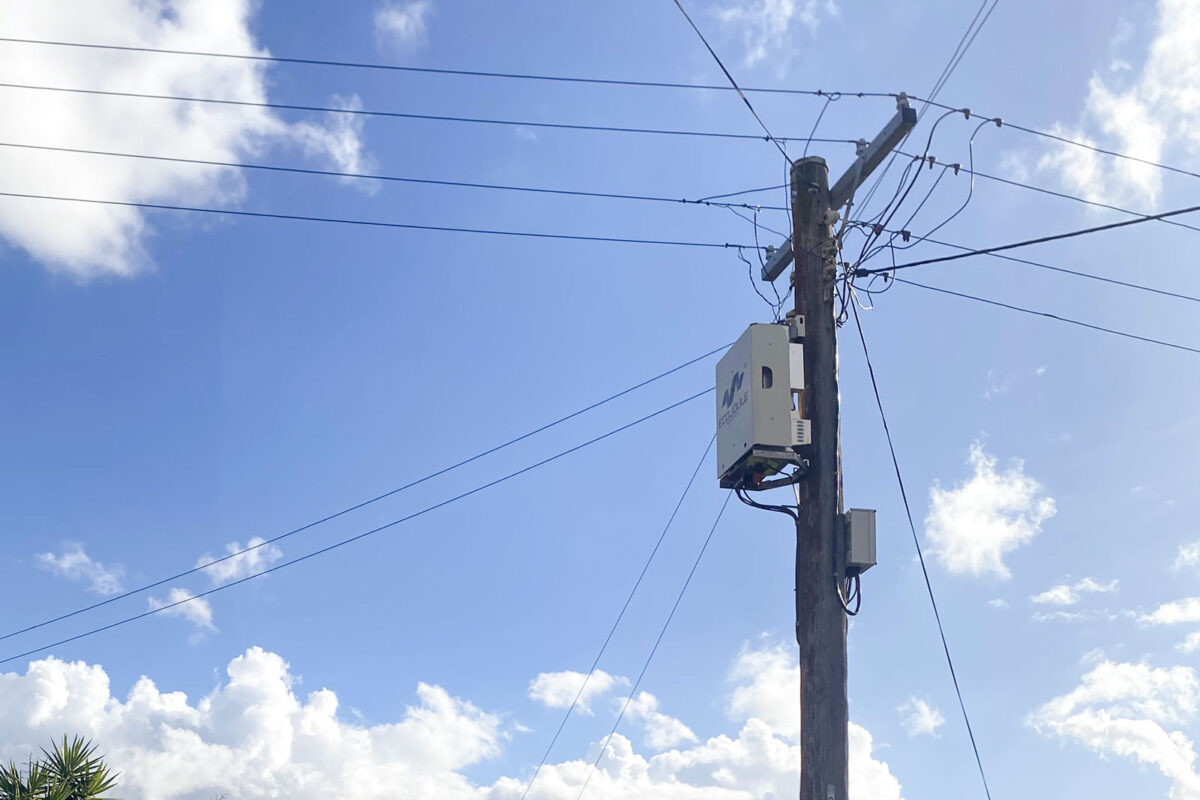
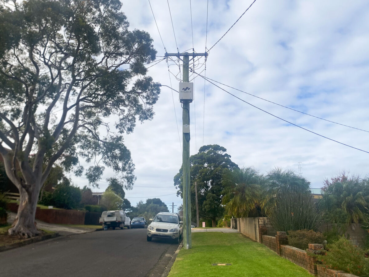
Dynamic phase balancing: fixing LV imbalance at the speed the load changes

Why service reallocation and augmentation no longer hold balance on feeders with single-phase EV charging, heat pumps and rooftop PV — and what a three-converter D-STATCOM does differently.

Phase imbalance on low voltage networks is not new. What has changed is the size and behaviour of the loads creating it, and the rate at which a balanced feeder becomes an unbalanced one.

Australian LV distribution is a four-wire multiple earthed neutral system, and almost every domestic connection is single phase. Historically that was manageable: individual loads were small, diversity across dozens of customers smoothed the per-phase totals, and a planner could allocate services across phases at connection and expect that allocation to hold for a decade.

Single-phase 7.2 kW EV chargers, heat pumps, electric hot water, reverse-cycle air conditioning and residential batteries break that assumption. One EV charger can represent more after-diversity demand than the five houses around it. Loads arrive where customers buy them, not where the network has headroom, and they cluster. One street adopts, the next does not. A feeder that measured within a few percent of balance at commissioning can sit 30 to 40 percent out on a winter evening, where the cold climate means that load diversity is simply all feeder heat pumps operating. Conversely, the imbalance moves during the day, as charging, hot water and cooling cycles overlap.

Unbalanced phase currents return through the neutral. In an MEN system the neutral is not a zero-volt reference; it carries current and develops a voltage along its length. That neutral shift moves the star point relative to the customer connections, so the heavily loaded phase drops further than its own load would explain, and the lightly loaded phases rise. The customer on phase C experiences a voltage complaint caused by loads on phase A.

The loss penalty follows the same currents.

ConditionPhase currentsNeutral currentConductor loss term
Unbalanced100 A / 60 A / 40 A53 A18,000 A²
Balanced66.7 A each0 A13,333 A²

Same total current delivered, unity power factor, equal phase and neutral conductor resistance. Balancing removes the neutral current and reduces conductor loss by approximately 26 percent.

WORKED EXAMPLE

Ia = 100 A at 0°    Ib = 60 A at −120°    Ic = 40 A at +120°

Real      = 100 − 30 − 20 = 50.0 A

Imaginary = −51.96 + 34.64 = −17.32 A

|In| = √(50.0² + 17.32²) = 52.9 A
Unbalanced: 100² + 60² + 40² + 52.9² = 18,000 A²

Balanced:   3 × 66.7² + 0²            = 13,333 A²

Reduction:  1 − 13,333 / 18,000 = 25.9%
Positive sequence         66.7 A  →  13,333 A²

Negative sequence         17.6 A  →     933 A²

Zero sequence (phases)    17.6 A  →     933 A²

Zero sequence (neutral)   52.9 A  →   2,800 A²

The distribution transformer is derated by the same mechanism: it reaches its thermal limit on the worst phase, not on its nameplate kVA. Imbalance therefore consumes three things a planner needs — voltage headroom, thermal capacity and network losses. It also consumes hosting capacity, because the same neutral shift that pulls one phase low pushes another high, and rooftop PV on that phase curtails first.

Service reallocation. A crew measures the pillar or the transformer over a week, identifies the loaded phase, and moves services across. It works, and it is inexpensive. It also requires a truck, a customer outage and a decision based on a snapshot. The measurement describes last month’s load pattern. The next EV connection, the next hot-water changeover or a shift in occupancy reverses it. Networks that rebalance on complaint are rebalancing the same feeders repeatedly.

Augmentation. A second transformer, reconductoring, or splitting the LV area fixes the peak with certainty. It also costs capital, takes months of design, easement and outage planning, and is sized for a load forecast that single-phase electrification keeps revising upward.

Conventional three-phase STATCOMs. A standard three-leg converter injects a balanced positive-sequence current. It can raise or lower all three phase voltages together, and it can correct power factor, but it cannot differentiate between phases. Applied to an unbalanced feeder it lifts the low phase and the already-high phases with it.

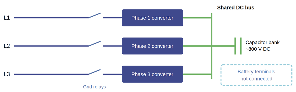
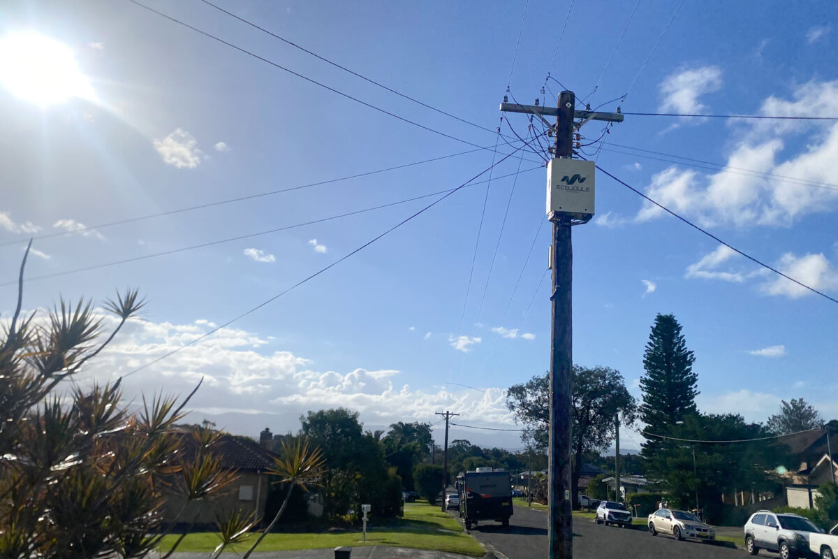
The EcoVAR is built as three independent single-phase STATCOM systems sharing a common DC bus. That architecture is the reason it can do something a conventional STATCOM cannot.

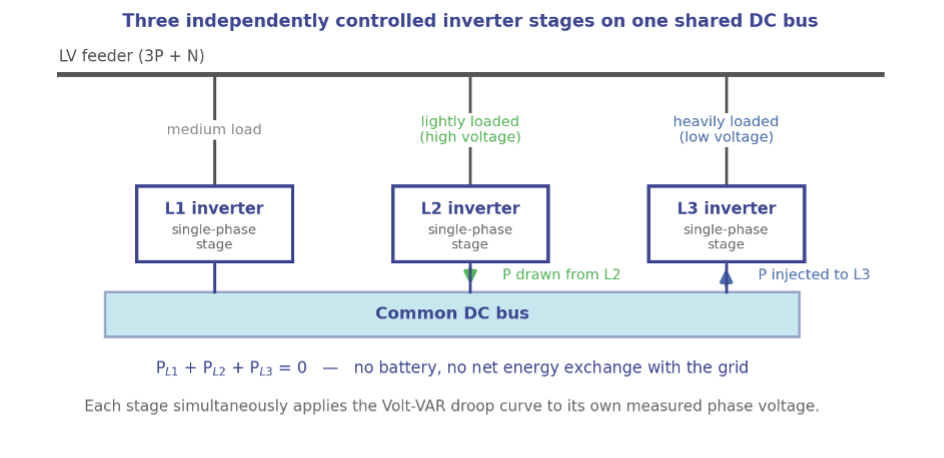
Because each phase has its own converter, the units can operate in opposite directions at the same instant. The converter on the heavily loaded phase supplies active power to the network; the converters on the lightly loaded phases absorb it. The shared DC bus is the transfer path. Net real power exchange with the network is close to zero, but the currents drawn from the transformer and the upstream conductor are balanced.

Active power balancing control manages this continuously. There are no discrete steps to select and no transformer taps to move. The device sets per-phase active and reactive current targets from the instantaneous measured condition and holds balance as the load profile changes through the day.

The control operates on instantaneous per-phase quantities rather than RMS values averaged over seconds, so correction occurs within a cycle.

This matters most for motor starting. A heat pump or air conditioning compressor draws several times its running current for a few cycles at start. On a weak single-phase connection that inrush produces a visible voltage dip, and through the neutral shift it disturbs the other two phases as well — the sag propagates to customers who did not cause it. A balancer that responds over seconds sees the event only after it has finished.

The EcoVAR supports the starting phase from the DC bus as the current rises, so the dip is contained at its source and does not couple across. The same mechanism handles PV inverter ramps, battery mode changes and EV charger step loads.

  • Balanced phase currents at the distribution transformer, held continuously rather than set once.
  • Neutral current and neutral voltage rise reduced, with the associated loss reduction.
  • Voltage spread between phases narrowed, recovering headroom for both load and PV export.
  • Sub-cycle containment of motor starts and step loads.
  • Installation on an energised network with no customer outage.
  • Per-phase measurement of the LV condition, available remotely, including after the correction is in service.

Phase imbalance created by single-phase electrification is dynamic. It changes hour to hour and grows year on year. Correction that is set manually, or that responds in seconds, is answering a question the network stopped asking. Dynamic balancing addresses it at the timescale it occurs, on the existing poles and wires.


EcoJoule Energy designs and manufactures low-voltage grid-edge power electronics in Brisbane, Australia. Its EcoVAR LV D-STATCOM is in field service with distribution utilities in Australia and internationally, and is available in pole-mount (EcoVAR Alto) and ground-mount (EcoVAR Terra) variants. EcoJoule’s technology relieves grid congestion and increases network hosting capacity, allowing the benefits of the energy transition to reach more users of the existing distribution network.
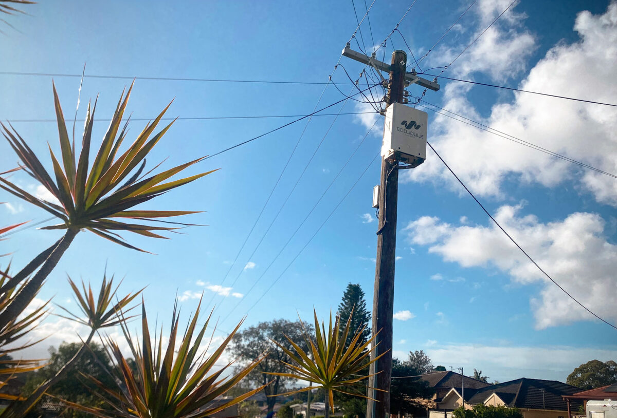
Network Planners’ Guide – The Smarter, More Economic Alternative to Network Augmentation

EcoJoule Energy’s Network Planners’ Guide explains how D-STATCOM technology provides network planners and engineers with a faster, more flexible and lower-cost alternative to conventional network augmentation, while improving voltage regulation, phase balance and power quality across increasingly complex distribution networks. Download the full guide here.

Executive Summary

Low-voltage electricity networks are under growing pressure from rooftop solar, electric vehicles, electrification and other distributed energy resources (DER), while much of the infrastructure supporting them was designed for a very different energy system.

The resulting overvoltage, undervoltage, phase imbalance, and power quality issues do not always indicate that a network has run out of capacity. Where the constraint is voltage or imbalance rather than thermal capacity, LV D-STATCOM technology such as EcoJoule Energy’s EcoVAR™ can provide a faster, more flexible alternative to traditional augmentation.

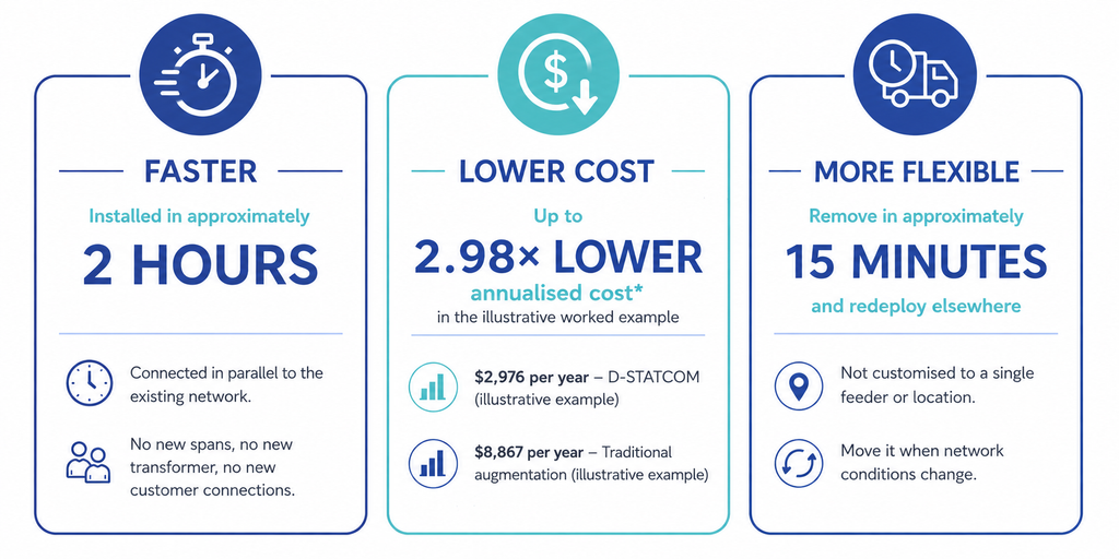
EcoVAR can be installed in approximately two hours with no customer outage, avoiding much of the engineering, construction and disruption associated with traditional network upgrades. In the illustrative example examined in this paper, the D-STATCOM solution delivers an annualised cost that is approximately 2.98 times lower than that of traditional augmentation. It can also defer major capital works and be redeployed as network requirements change.

The opportunity is not to replace augmentation where additional thermal capacity is genuinely required. It helps match investment to actual constraints, solve problems sooner, deploy capital more efficiently, and get more from existing network infrastructure.

D-STATCOM or Traditional Augmentation?

Traditional augmentation means reconducting LV lines, installing new transformers, or extending the medium-voltage supply to split feeders and shorten LV runs. Manual phase balancing, moving single-phase customer connections between phases, is also a form of augmentation.

A D-STATCOM is a form of augmentation. It requires no new HV line, no outage, and installation is under two hours. The engineering design is standard for all installations on a given network.

The limitation is explicit: a D-STATCOM does not add thermal capacity. Only augmentation does that.

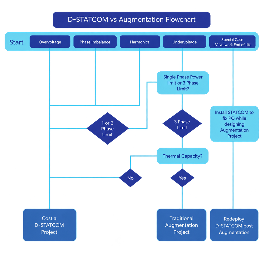
Most voltage, imbalance and harmonic problems can be resolved without adding capacity. That is the selection test.

Three differences matter to a planner.

1. Speed – Connected in parallel to the existing network. No new spans, no new transformer, no new customer connections. Installed and commissioned in two hours. Augmentation projects run in days or weeks and include a customer outage.

2. Project Cost – The unit cost is comparable to that of a single transformer. The difference is the project around it: engineering design, outage management, traffic management, and construction lead time.

3. Redeployment – When capacity becomes the binding limit, an installed D-STATCOM can be moved. It is not customised to a site. Removal takes 15 minutes, and reinstallation takes two hours. Augmentation is fixed to the site where it is built.

Where a D-STATCOM Applies

A D-STATCOM, such as EcoJoule Energy’s EcoVAR, connects in parallel with the existing LV network and directly addresses voltage imbalance and harmonic problems. The technology is particularly applicable where the network is experiencing:

  • Overvoltage – Often associated with high levels of rooftop PV exporting onto an LV feeder.
  • Phase imbalance – Created when load and generation are unevenly distributed across the three phases.
  • Harmonics – Increasingly relevant as inverter-based and power-electronic devices proliferate.
  • Undervoltage on one or two phases – Where available capacity exists elsewhere across the three-phase network.
  • Voltage sags, swells and flicker – Where dynamic voltage support can improve local power quality. 

Selection Guide

Observed problemOutcomeReason
OvervoltageCost a D-STATCOM projectActive power is not the limit, so the device always has authority.
Phase imbalanceCost a D-STATCOM projectAt least one phase carries excess active power. Active phase transfer corrects it.
HarmonicsCost a D-STATCOM projectHarmonic correction is not limited by active power.
Undervoltage on one or two phasesCost a D-STATCOM projectA single-phase power limit. Correctable by transfer between phases.
Undervoltage on all three phasesTraditional augmentation projectA thermal capacity limit. A D-STATCOM does not add capacity.
LV network at end of lifeBoth, in sequenceInstall the D-STATCOM to hold power quality while the augmentation is designed, then redeploy it.

Calculating the Benefits

The real cost of solving an LV network constraint extends well beyond the upfront price of the equipment.

Traditional augmentation may deliver infrastructure with an asset life measured in decades, while a D-STATCOM has a shorter life but offers something conventional infrastructure cannot: the flexibility to be removed and redeployed as network needs change.

A simple capital-cost comparison therefore does not compare like with like. A more meaningful approach is to compare the cost of delivering the required network outcome over time.

Equivalent Annual Cost (EAC) provides that comparison by annualising each component according to its cost, expected asset life and discount rate:

EAC = C ÷ [(1 − (1 + r)^-n) ÷ r]

Each project component retains its own asset life, allowing long-life infrastructure, engineering, installation and equipment costs to be assessed consistently. This provides planners with a clearer picture of the long-term economics of each approach rather than focusing solely on initial capital expenditure.

The Value of Deferring Augmentation

The decision is not always D-STATCOM or traditional augmentation. Where additional thermal capacity will eventually be required, a D-STATCOM can address the immediate voltage or phase constraint while allowing major augmentation to occur when that additional capacity is actually needed.

Deferral can postpone significant capital expenditure, potentially move investment into a future regulatory period and provide more time to understand how DER penetration and demand will develop.

Importantly, the investment does not have to become stranded when augmentation eventually occurs. If the D-STATCOM still has useful service life, it can be redeployed to another constrained feeder, extending the value of the original investment.

The objective is not to avoid necessary augmentation. It is to solve today’s constraint efficiently, preserve future options and invest in permanent network capacity when the network actually needs it.

How a D-STATCOM Works

The D-STATCOM is a three-phase power electronic device connected to the LV network in parallel. It is three independently controlled inverter-STATCOMs, one per phase, with a common shared 864V nominal DC bus.

Two control actions run at the same time.

  • Reactive Injection – The unit exchanges reactive current with the network at the point of connection. The voltage change is approximately: ΔV ≈ Q·X / V, where Q is the injected reactive power, X is the upstream reactance and V is the nominal voltage. The unit works against upstream impedance. More upstream reactance gives more voltage authority.
  • Active Phase Transfer – The unit moves real power between phases through a shared DC bus. This corrects imbalance directly rather than compensating negative sequence current alone. Active harmonic filtering runs on the same hardware, injecting harmonic current in antiphase.
Expected Voltage Correction

Worked case: 95 mm² aluminium overhead conductor, R ≈ 0.32 Ω/km, X ≈ 0.29 Ω/km, X/R ≈ 1, 1 MVA distribution transformer, 40 kVAr device.

Distance from transformerVoltage correctionAs percentage
500 m≈ 16 V4.00%
750 m≈ 22.5 V5.60%

Transformer rating has little effect at the feeder end. At 750 m, line reactance is about 95% of total upstream reactance, so a 500 kVA and a 1 MVA transformer give nearly the same result.

Two limits apply. Reactive injection does not correct voltage drop caused by real load current through line resistance. On an underground cable, X/R is lower and correction per kVAr is lower than the figures above.

D-STATCOMs still work in both cases, but the total voltage change per unit may be lower. Multiple STATCOMs can be connected to the same LV network to increase power if necessary. It is rare, even on aerial bundled conductor (ABC) networks, to need more than one 40 kVAr unit per LV feeder.

Site Selection

Place the unit near the voltage or imbalance problem. Most installations fall between 50% and 80% of the way along the LV feeder, but that range is a guide rather than a rule. Position follows the problem.

Move toward 50% where PV generation is concentrated in the middle of the feeder, or where the LV line can be backfed. Move toward the far end where the deviation is worst at the end. A shift of a few spans either direction makes no material difference to the result.

Within that zone, select the cheapest site to build. Where the electrically preferred pole carries streetlighting, fuses or telecommunications equipment, or where vegetation restricts access, move to the next clean pole. Installation cost dominates the difference; electrical position does not.

Where smart meter data is available, use it to identify the spans and phases with the most frequent and most severe deviations. This reduces selection to a short list of candidate poles.

Voltage is held closest to setpoint at the point of connection, but the effect is seen along the whole feeder.

A head-end tap changer translates the entire profile: it can be set for midday or for evening, not both. A D-STATCOM at the constrained node holds that node at setpoint and reverses between absorbing and injecting as conditions change.

Connecting a D-STATCOM to the Network

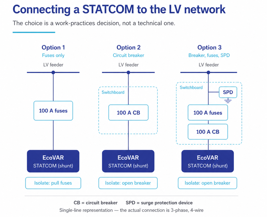
The unit connects in shunt. The feeder continues to carry its load and does not need to be de-energised to connect or remove the unit. There is no customer outage.

Every shunt connection needs overcurrent protection and a means of isolation. Three arrangements are used. All three perform identically. The choice is a work practices decision, not a technical one.

ArrangementIsolation methodWhen it is used
Outdoor fusesPull the fusesLowest cost, fewest components. Not available where technicians may not pull live LV fuses.
Switchboard with circuit breakerOpen the breakerWhere live fuse pulling is prohibited by work practices.
Switchboard with breaker, backup fuses and SPDOpen the breakerWhere surge protection is required by network standard.

Rating is 100 A, whether fuse or breaker. Rated current is 63.5 A continuous, with short-time capability of 1.5 × rated, approximately 95 A. Most off-the-shelf MCBs derate at elevated ambient temperature. At the unit’s 50°C maximum, a marginally sized breaker can trip at full output. A 100 A device holds margin above the derated threshold while remaining low enough to protect the connection. Confirm that the shunt connection conductors are rated to carry 100 A.

Notes for Protection Engineers

  • The D-STATCOM is not an energy storage device. It sources power from the line side. Loss of phase or loss of supply removes it from the circuit.
  • Onboard capacitors discharge over approximately one minute on loss of mains.
  • The protective device on the overhead connection is 100 A, fuse or MCB, subject to work practices.
  • Anti-islanding is handled by internal relays. Undervoltage and underfrequency disconnect settings are configurable and are shipped to IEC 62477 inverter settings.
  • As a utility-grade device, the disconnect range is often widened on commissioning. This allows the unit to correct voltage during a sag rather than disconnecting, and to connect to a non-compliant voltage and then bring it into compliance.
  • The tests highlighted in this white paper are intended to be run by the planner on network data and cost data that the planner controls.
  • A D-STATCOM will not suit every site. Where the constraint is thermal, it does not apply. Where it does apply, the annualised cost comparison should be run and recorded either way.

For More Information

Martin van der Linde
Chief Commercial Officer
EcoJoule Energy Pty Ltd
sales@ecojoule.com

Volt-VAR Droop and Active Power Balancing in the EcoVAR LV STATCOM

How the two simultaneous control loops in a three-phase LV STATCOM work, and what each one can and cannot correct.

1. Summary

  • The EcoVAR uses three independently controlled single-phase inverter stages connected to one shared DC bus.
  • A Volt-VAR droop curve sets reactive power as a function of measured voltage. The EcoVAR evaluates that curve against each phase voltage separately, so one phase can absorb VArs while another injects them.
  • A second loop, Active Power Balancing, runs at the same time. It moves real power from lightly loaded phases to heavily loaded phases through the shared DC bus.
  • The two loops correct different things. Reactive power shifts each voltage as well as the average voltage; active power transfer corrects the difference between phases and reduces neutral current. Neither substitutes for the other.
  • Both loops operate from voltage measurement only. No series current transformers are required, so installation does not depend on breaking the conductor.

2. What a Volt-VAR droop curve does

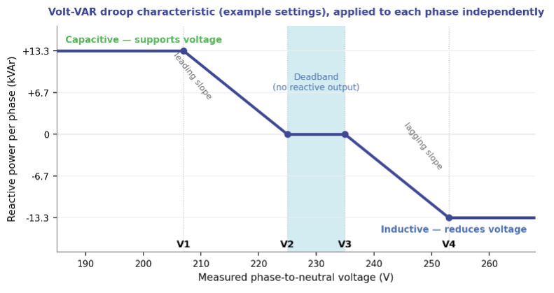
A Volt-VAR droop curve is a piecewise-linear rule that converts a measured voltage into a reactive power command. It is defined by four voltage set points and applied continuously, without operator intervention or a network communications link.

Below the lower set point the STATCOM sources reactive power (capacitive operation), which raises voltage at the point of connection. Above the upper set point it sinks reactive power (inductive operation), which lowers voltage. Between the two inner set points the output is zero. That deadband stops the unit from responding to normal small voltage variations.

The EcoVAR follows the generator sign convention: a positive reactive power reference is capacitive (sourcing VArs), a negative reference is inductive (sinking VArs). The characteristic is as described in AS/NZS 4777.2:2020 and similar international standards like EN50549, with leading and lagging slopes that can be set symmetrically or asymmetrically.

Figure 1 — Volt-VAR droop characteristic. Set points shown are an example only.

3. Configurable set points

All four set points are user-configurable from the EcoVIEW engineering tool or by uploading a settings file through EcoFLEET Manager. A limited set is also available over DNP3 and Modbus.

Set pointRangeFunction
V1180 – 225 VAt and below V1 the phase holds maximum capacitive output.
V2185 – 250 VLower edge of the deadband. Capacitive output falls linearly from V1 to zero at V2.
V3185 – 260 VUpper edge of the deadband. Inductive output starts here.
V4190 – 277 VAt and above V4 the phase holds maximum inductive output.

Rated output is 40 kVAr total, 13.33 kVAr per phase, available in both directions across 210 V to 277 V. The unit continues to operate down to 180 V at a maximum continuous 63.5 A per phase, and tolerates connection to any voltage from 0 V to 280 V without damage.

4. Three inverter stages, one DC bus

The EcoVAR is not a single three-phase bridge producing a balanced output. Each phase is served by an inverter stage with its own current control loop, and all three stages are connected to a common DC bus. Two consequences follow directly from that architecture.

First, each stage can be commanded independently. The droop curve is evaluated three times each control cycle, once per phase, against that phase’s own measured phase-to-neutral voltage. One phase reaching its current limit does not constrain the other two.

Second, active (real) power can be moved between phases. Because the three stages share a DC bus, power drawn from one phase can be injected into another without a battery and without any net exchange of energy with the network.

Figure 2 — Active power transfer between phases through the shared DC bus.

5.  A single characteristic, three independent evaluations

The three phases share one droop characteristic — the same four set points and the same slopes apply to all of them. What is independent is the input and the output, not the configuration. Each stage measures its own phase voltage and produces its own reactive power command from the shared curve.

This is what allows the EcoVAR to reduce voltage unbalance rather than simply shift the whole voltage profile. On a feeder where L1 sits at 252 V under high PV export and L3 sits at 228 V under load, the same curve puts L1 into full inductive operation and L3 into capacitive operation at the same instant.

The unit can alternatively be configured to act on the average of the three phase voltages. That mode is available for networks whose standards require it, but it gives a poorer voltage outcome for customers and is not the recommended setting.

6.  The second loop: Active Power Balancing

Reactive power alone corrects voltage well on reactive networks. On resistive LV networks — underground cable, long aluminium mains, heavily loaded urban feeders — voltage responds more strongly to real power than to reactive power, and reactive injection alone cannot bring the phases together.

Active Power Balancing addresses this. The EcoVAR takes the three phase voltages as a proxy for phase loading: a higher voltage implies a lighter load, a lower voltage implies a heavier one. It then transfers real power from the lighter phases to the heavier ones in proportion to the voltage differences, subject to the constraint that the three phase powers must sum to zero. This reduces current unbalance on the feeder and neutral current at the transformer.

Using voltage as the proxy avoids series current transformers. That removes both the cost and the outage that a CT installation would otherwise require.

Two modes are provided. Gain-based transfer injects real power per phase in proportion to the deviation from the average voltage, with a user-selected P or Q priority that determines which is curtailed first if a phase reaches its apparent power limit. Optimal X/R computes a reference apparent power per phase from a voltage droop and then splits it into active and reactive components according to the source impedance X/R ratio, which is taken from the network model or estimated at commissioning. Active Power Balancing is disabled by default and is enabled per site.

7.  Why both loops are needed

The two loops are subject to different constraints, and that is the whole reason for running them together.

 Volt-VAR droop (Q)Active power balancing (P)
Quantity controlledReactive power per phaseActive power transfer between phases
Network constraintLimited only by the per phase apparent power rating of the unitSum of the three phase powers must be zero
Effect on average voltageCan raise or lower all three phases togetherNone — the three voltage changes sum to zero
Effect on unbalanceReduces it, most effectively on reactive networksReduces it, most effectively on resistive networks
Effect on neutral currentIndirectDirect reduction at the transformer
Default stateEnabledDisabled — enabled per site

If all three phase voltages are high, transferring real power between them cannot bring any of them down, because whatever one phase gains another must lose. Only reactive power can move the average. Conversely, on a resistive feeder with one badly loaded phase, reactive power struggles to close the gap and real power transfer does it efficiently. Running both loops covers both cases across the full range of LV network impedances.

8.  Control loop timing

FunctionResponse
Internal current control loop10 – 90% rise and fall in 2 ms or less
Volt-VAR droop response (ramp-rate limited)Default 5 s, to keep the steady-state response smooth. However, can be set sub-cycle for fast response, typically when Active Power Balancing is disabled.
Voltage sag and swell limiting10 ms time constant; overrides the droop response
Reactive current overshootNo more than 5% of steady-state output

The current loop is fast enough to respond within a tenth of a cycle. The droop response is deliberately slowed to five seconds so that the unit regulates steady-state voltage rather than chasing transients. Fast events are handled separately: if a phase reaches 180 V or 277 V, the sag and swell function commands maximum reactive power with a 10 ms time constant and overrides the droop.

9.  What to specify at commissioning

  • Four droop set points, plus symmetrical or asymmetrical slopes.
  • Per-phase control enabled, or average-voltage mode if a network standard requires it.
  • Active Power Balancing: disabled, gain-based, or optimal X/R.
  • For gain-based operation: P priority or Q priority, chosen from the local X/R ratio — Q priority for overhead and other reactive feeders, P priority for cable and other resistive feeders.
  • For optimal X/R operation: the X/R ratio, from the network model or estimated during commissioning.

For settings files, network studies or a copy of the EcoVAR ALTO user manual, contact EcoJoule Energy at sales@ecojoule.com or your regional distributor.  

EcoJoule Adds Malaysia To Growing Global Footprint

Australian energy grid technology company EcoJoule Energy has secured its first sale into Malaysia, marking another significant milestone in the company’s international expansion and adding one of Southeast Asia’s most important electricity markets to its growing global footprint.

The sale to Tenaga Nasional Berhad (TNB), Malaysia’s national electricity company and operator of the electricity grid throughout Peninsular Malaysia and Kuala Lumpur, includes multiple EcoVAR™ ALTO pole-mounted STATCOMs and EcoSTORE™ pole-mounted Battery Energy Storage System (BESS) units.

The first shipment of EcoVAR units left Australia this week, with the EcoSTORE units to leave in approximately eight weeks.

The agreement further expands EcoJoule Energy’s international presence, which now spans almost ten countries, including Australia, New Zealand, Hong Kong, Belgium, Spain, the United Kingdom, Lithuania, Israel and now Malaysia.

EcoJoule Energy Founder and CEO Dr Mike Wishart said the new sale reflected growing global demand for technologies that help electricity networks manage the growth of renewable energy and the impact on the energy grid.

“Malaysia represents an important new market for EcoJoule and demonstrates the increasing international recognition of Australian innovation in electricity network management,” Dr Wishart said.

“Across the world, network operators are facing many of the same challenges. As solar penetration continues to increase, particularly on distribution networks, utilities need smarter and more flexible ways to manage voltage stability and power quality.”

“We are seeing strong demand for STATCOM technologies because they provide a highly effective solution for maintaining grid stability, while enabling greater levels of renewable energy integration.

“Utilities are looking for practical, cost-effective tools that help them manage the energy transition without relying solely on traditional network augmentation that can cost tens of millions of dollars.”

“The challenges facing electricity networks in Asia, Europe and Australia share a common theme – the transition to cleaner energy is creating increasingly dynamic and complex power flows. EcoJoule’s technologies are designed specifically to help networks adapt to that transition efficiently and sustainably.”

Solving Complex, Pressing Grid Issues

EcoJoule Chief Commercial Officer Martin van der Linde said the Malaysian deployment highlighted the versatility of the company’s technology platforms and its ability to address a broad range of network challenges.

“Our EcoVAR and EcoSTORE platforms have been developed to solve some of the most pressing issues facing modern electricity networks,” Mr van der Linde said.

“What makes the technology unique is its ability to address multiple challenges through a flexible, pole-mounted solution that can be rapidly deployed where it is needed most.”

“Whether utilities are dealing with voltage variability caused by rooftop solar, phase imbalance, peak demand constraints, increasing electrification, or the need for distributed energy storage, our technology provides network operators with greater visibility, control and flexibility.”

“The global energy transition is creating increasingly complex energy flows throughout distribution networks. EcoJoule’s solutions help operators manage that complexity while maximising the use of existing infrastructure and improving reliability for customers.”

EcoVAR™ is a pole-mounted Static Synchronous Compensator (STATCOM) that uses advanced power electronics and software to regulate voltage and reactive power on low-voltage networks in real time. The technology enables network operators to integrate greater levels of distributed renewable energy and electrification technologies while improving power quality and reducing the need for costly network upgrades.

EcoSTORE™ is EcoJoule’s pole-mounted battery energy storage platform, designed to provide distributed storage capacity within local electricity networks. The system helps manage peak demand, supports renewable energy integration, improves network resilience and enables more efficient utilisation of grid infrastructure.

The Malaysian project follows a series of successful deployments of EcoJoule technologies across Australia and international markets, reinforcing the adaptability of the company’s solutions across diverse network conditions and regulatory environments.

Established nearly a decade ago, EcoJoule Energy is a 100 per cent Australian-owned company providing innovative solutions that help electricity distributors integrate renewable energy, improve power quality and manage grid reliability.

Why D-STATCOMs deliver faster fixes for Low Voltage Network Power Quality

A D-STATCOM (Distribution LV STATCOM) and a feeder augmentation can both bring an LV feeder back inside voltage limits. They differ in how much engineering, land access and switching work sits between identifying the problem and the network being compliant. Four reasons the D-STATCOM path is shorter.

1. A D-STATCOM uses the existing poles and wires

An augmentation project changes the network’s physical assets. That means a feeder civil design: pole loading and strength assessment, conductor selection, clearance checks, possible easement or land acquisition for a new substation site, and design approval before any works order issues.

A D-STATCOM changes the network’s electrical behaviour without changing its topology. The EcoVAR Alto mounts on an existing pole; the EcoVAR Terra sits on a pad. Both connect to the existing LV mains. No conductor replacement, no new feeder route, no land acquisition. The civil design and land access critical path is removed, not shortened.

2. D-STATCOMs connect in parallel, not in series

A series device sits in the supply path. Installing it requires an LV outage, customer notification and a switching programme, and once installed it becomes a single point of failure between the transformer and the customer.

A D-STATCOM connects in parallel through its own protection. Consequences for delivery:

  • Installation is a live connection — no planned outage, no notification process, no switching programme.
  • An internal device fault operates the device’s protection and disconnects the unit. Supply to customers is unaffected; the network returns to its pre-installation condition.
  • No new customer-interruption failure mode is introduced into the supply path, so the reliability case is straightforward.

3. One construction design per LV line type, used network-wide

The D-STATCOM installation is feeder-agnostic. The arrangement depends on the line construction, not on the feeder’s loading, length or fault level.

In practice, standards teams develop one standard arrangement per LV construction type in their network — bare conductor, aerial bundled conductor, underground pad-mount — and then apply it everywhere. Design effort becomes a one-off standards exercise rather than a per-project one. Once the standard arrangement exists, each subsequent site is a works order, not a design job.

4. The settings are generally common to every site but can be easily modified if required

The EcoVAR combines two control systems in one unit:

  • Volt-VAR reactive control for voltage regulation and power factor.
  • Simultaneous active power balancing control (patented) that transfers real power between phases to correct imbalance and neutral current.

Both controls act in closed loop on conditions measured at the point of connection. They are generally not tuned to a modelled feeder, so the setting file does not change site to site. One approved setting file covers the network. On occasions, for unusual sites (eg. Excessively weak low voltage feeders) the settings can be easily remotely modified.

That has direct operational consequences: spares are interchangeable across the fleet, a hot swap needs no re-engineering, and a crew can redeploy a unit from one site to another without a new study.

The net effect

The first D-STATCOM deployment carries the standards work: one arrangement per line type, one approved setting file. Every deployment after that is procurement plus a works order. Augmentation repeats the design, approval and outage cycle at every site.

Next step: EcoJoule can provide sample GA drawings for EcoVAR D-STATCOM installations, together with standard configuration for the Volt-VAR Droop curve. Contact EcoJoule for more information.